Hearing aid with tuned microphone cavity

a microphone cavity and hearing aid technology, applied in the field of hearing aids, can solve the problems of difficulty in hearing soft sounds at high audible frequencies, poor sound quality, and high cost of many components of these devices, such as signal processing circuitry, and achieve the effect of generalized cavity geometry control

Inactive Publication Date: 2010-07-13
HIMPP
View PDF81 Cites 43 Cited by
  • Summary
  • Abstract
  • Description
  • Claims
  • Application Information

AI Technical Summary

Benefits of technology

[0010]An advantage of the present hearing aid is that the tuned resonant cavity can be designed to provide a frequency response(s) that help compensate for various types of hearing loss. For instance, the tuned resonant cavity can be designed to increase the gain at higher frequencies relative to lower frequencies in the incident sound signal, since one common type of hearing impairment is a difficulty in hearing low-volume, high-frequency sounds. The tuned resonant cavity can help reduce the cost of the hearing aid, since the passive conditioning of the incident sound waves afforded by the tuned resonant cavity minimizes the requirements of the signal processing electronics. Thus, smaller, less complex, and / or less expensive circuitry can be employed. In addition, because the tuned resonant cavity is a passive component that does not consume any electrical power, the power requirements of the hearing aid are reduced. This is particularly important in the context of a disposable hearing aid, since lower power requirements translate to a longer useful life for the hearing aid.

Problems solved by technology

For example, one common type of hearing impairment is the difficulty in hearing soft sounds at high audible frequencies.
A limiting factor on the development of high-quality, inexpensive hearing aids is that many of the component parts of these devices, such as the signal processing circuitry, remain relatively expensive.

Method used


Image

  • Hearing aid with tuned microphone cavity
  • Hearing aid with tuned microphone cavity
  • Hearing aid with tuned microphone cavity

Examples


Embodiment Construction

[0027]A description of preferred embodiments of the invention follows.

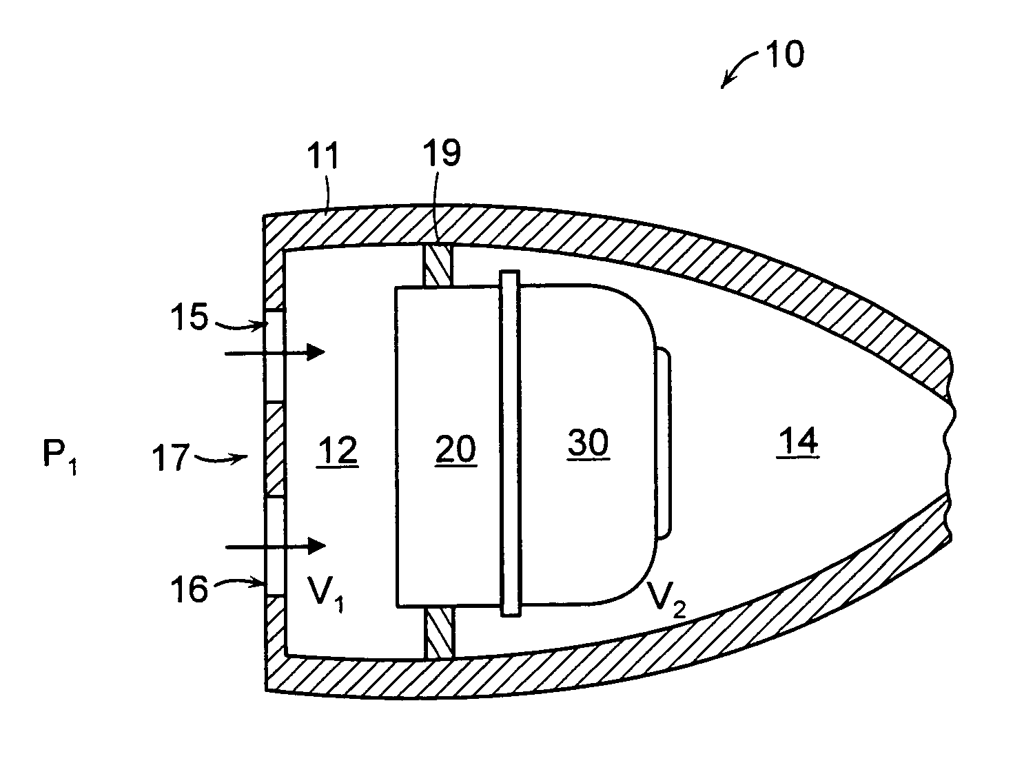
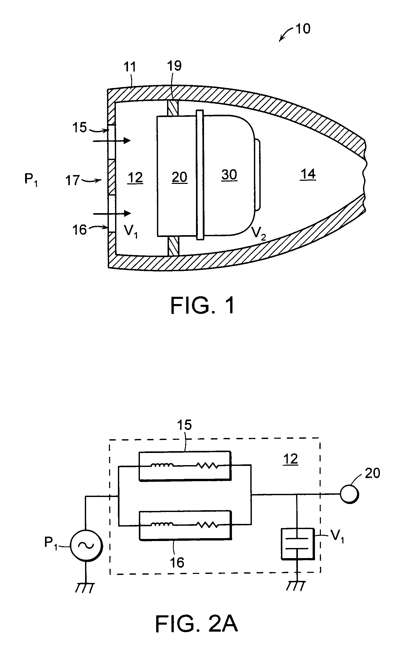
[0028]A hearing aid 10 having a tuned resonant cavity 12 is shown in FIG. 1. As shown in this figure, the hearing aid 10 includes a hearing aid shell 11 that contains various hearing aid components, such as a microphone 20 and battery 30, as is known in the art. The hearing aid shell 11 includes a face plate 17 located at the front end of the device. The face plate 17 includes a pair of openings 15, 16 that allow air and sound into the tuned resonant cavity 12. The resonant cavity 12 is tuned by selecting one or more parameters of the cavity, including the number, shapes and sizes of the openings 15, 16, and the shape and volume of the chamber 12. Additionally, the cavity can be tuned by selecting the number, shapes and sizes of any opening(s) between the chamber 12 and the microphone 20. By adjusting these parameters, the cavity 12 can effectively “tune” the incident sound wave signal, P1, to provide a desired fr...


PUM


Abstract

A hearing aid comprises a microphone that receives incident sound waves from one or more sources external to the hearing aid, and converts the sound waves into electronic signals; a circuit that amplifies the electronic signals; a receiver that converts the amplified electronic signals into amplified sound waves; and a tuned resonant cavity between the microphone and the at least one external sound source. At least one parameter of the tuned resonant cavity is selected to modify the frequency response of the incident sound waves that are received by the microphone. In particular, the geometry of one or more openings through which sound waves enter the chamber, the geometry of the chamber itself, and / or the geometry of one or more openings through which sound waves exit the chamber, are selected to condition the incident sound waves by modifying the frequency response of the audio signal prior to the signal being received at the microphone.

Description

RELATED APPLICATIONS[0001]This application is related to a co-pending U.S. Utility application Ser. No. 11 / 343,969, filed Jan. 30, 2005 entitled “Hearing Aid Circuit With Integrated Switch and Battery,” in the name of Walter P. Sjursen, Michael DeSalvo, Hassan A. Mohamed, Paul J. Mulhauser, and Karl D. Kirk III. This application is also related to a co-pending U.S. Design Pat. No. 29 / 253,043, filed Jan. 30, 2006 entitled “Hearing Aid,” in the name of Walter P. Sjursen, Michael DeSalvo, Hassan A. Mohamed, Paul J. Mulhauser and Karl D. Kirk, III. The entire teachings of the above applications are incorporated herein by reference.BACKGROUND OF THE INVENTION[0002]A hearing aid, in general, comprises a housing or ear mold which contains a receiver, a microphone, electronic circuitry connecting the receiver and the microphone, and a battery for operating the electronic circuitry. The housing is an ear mold which fits into the ear canal of the user.[0003]In a conventional hearing aid, the ...

Claims


Application Information

Patent Timeline
Patent Type & Authority Patents(United States)
IPC IPC(8): H04R25/00
CPCH04R25/48
Inventor SJURSEN, WALTER P.DESALVO, MICHAELMOHAMMED, HASSAN A.
Owner HIMPP
Why Eureka
Try Eureka