Extending and retracting device for vehicle step

a technology of extending and retracting devices and vehicle bodies, which is applied in the direction of steps arrangement, vehicle components, transportation and packaging, etc., can solve the problems of difficulty in meeting the trafficability and convenience the level cannot meet the trafficability requirements of most vehicles, and the extending and retracting device is difficult to meet the requirements of convenience and trafficability, so as to facilitate the extending and retracting action and eliminate stress concentration. , the effect of cost saving

Active Publication Date: 2010-05-11
HANGZHOU TIANMING TECH CO LTD
View PDF33 Cites 47 Cited by
  • Summary
  • Abstract
  • Description
  • Claims
  • Application Information

AI Technical Summary

Benefits of technology

[0009]One advantage of the extending and retracting device for a vehicle step of the present invention is that it provides increased reliability and reduced cost and structural complexity.
[0010]Another advantage of the extending and retracting device for a vehicle step of the present invention is that it distributes stress evenly with a buffering structure that is structurally simple.
[0012]Another advantage of the extending and retracting device for a vehicle step of the present invention is that end portions of the arc slot limit movement of the arc sliding member within the arc slot and buffer impact of the arc sliding member against the arc slot.
[0013]Another advantage of the extending and retracting device for a vehicle step of the present invention is that it produces an internal self-locking force that produces a balanced stage when the device is in its extended position.
[0014]Another advantage of the extending and retracting device for a vehicle step of the present invention is that the arc sliding member and arc slot eliminate stress concentration so that useful life of the device is long.
[0015]Another advantage of the extending and retracting device for a vehicle step of the present invention is that it is relatively lightweight.

Problems solved by technology

However, it is difficult to meet the trafficability and convenience requirements simultaneously when mounting the vehicle step.
In terms of ergonomics, the vehicle step is generally mounted at a level of 15 cm with respect to the ground so that it is convenient for a passenger of the vehicle to get on or off it, but this level cannot meet the trafficability requirements of most vehicles.
However, this extending and retracting device suffers from at least two disadvantages.
First, the distance between two pivot shafts connecting the four-link mechanism and the vehicle step is short so that stress tends to concentrate on the pivot shafts' position when a passenger steps on the extended vehicle step.
Thus, the pivot shafts tend to be destroyed over time due to their lack of mechanical strength.
Therefore, reliability is reduced, and cost is increased.
Second, the retractable vehicle-step apparatus employs a buffering structure in the form of a stopping block, thus increasing the complexity of the apparatus.

Method used


Image

  • Extending and retracting device for vehicle step
  • Extending and retracting device for vehicle step
  • Extending and retracting device for vehicle step

Examples


first embodiment

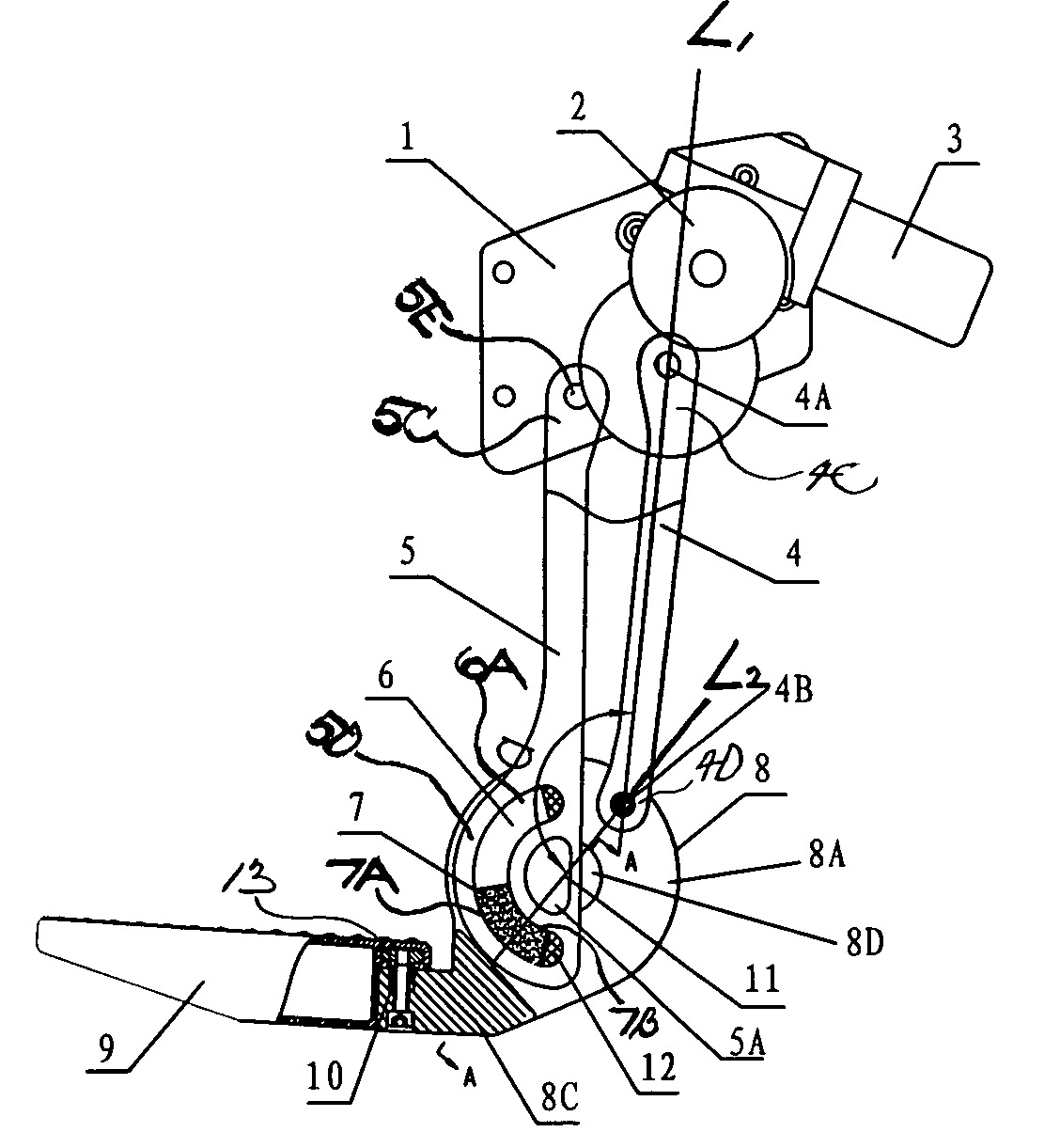
[0032]With reference to FIGS. 1-2 and 9, the device of the present invention will now be described. In general, this embodiment of the device includes a mounting bracket 1 adapted to be fixed to a body of a vehicle (not shown) and a step bracket 8. An arc sliding member 7 is fixed to the step bracket 8. A driving arm 4 defines a pair of ends 4C, 4D of the driving arm 4 pivotally connected to the mounting bracket 1 and step bracket 8, respectively. A supporting arm 5 defines an upper end portion 5C of the supporting arm 5 pivotally connected to the mounting bracket 1 and a lower end portion 5D of the supporting arm 5 defining at least one arc slot 6 of the lower end portion 5D. The arc sliding member 7 is adapted to fit into the arc slot 6 so as to be slidable in the arc slot 6 such that the lower end portion 5D of the supporting arm 5 is slidably connected to the step bracket 8.

[0033]More specifically, the step bracket 8 includes a body portion 8A and an extension portion 8C extendi...

second embodiment

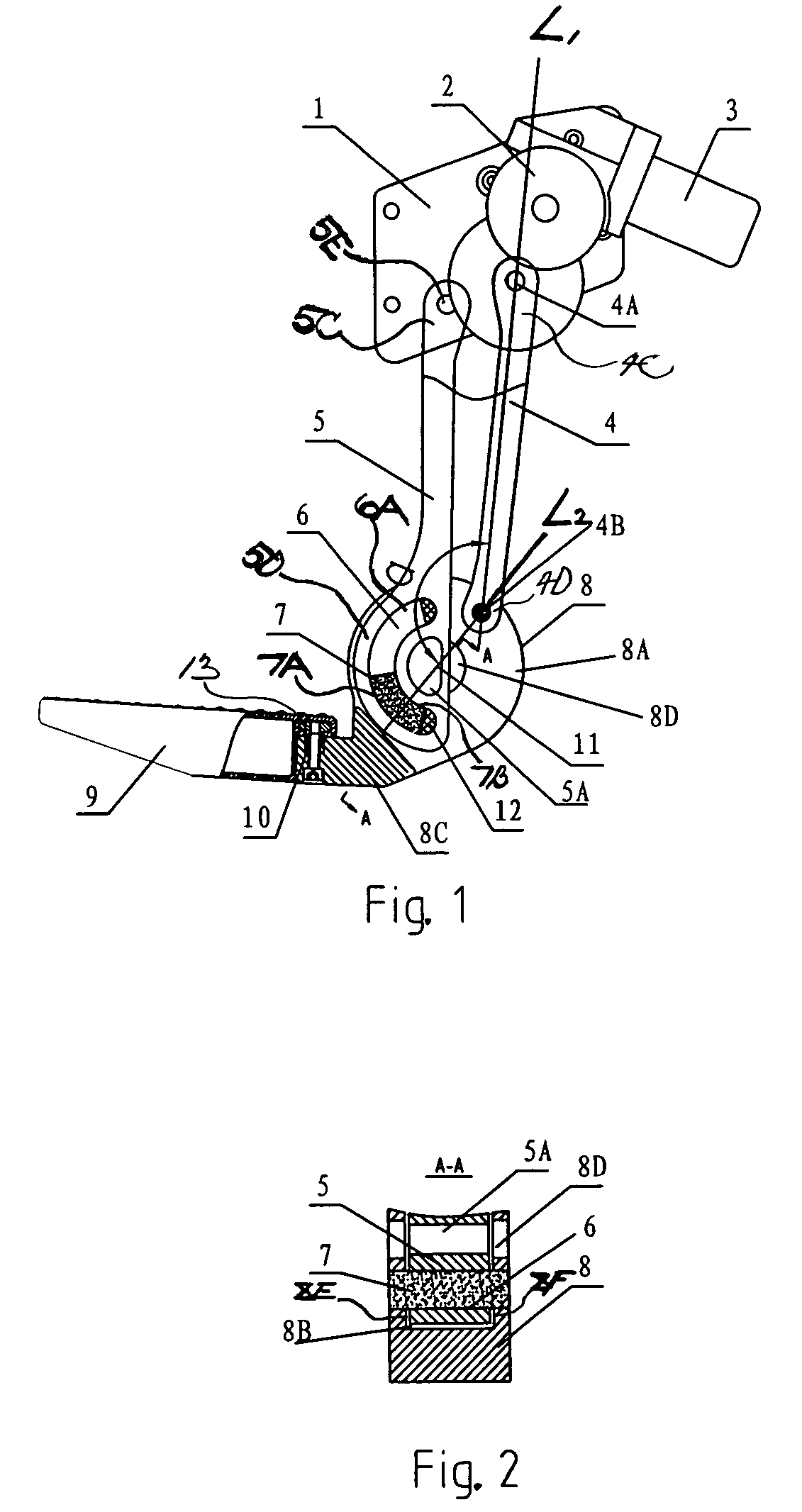
[0042]With reference to FIGS. 3-4 and 10, the device of the present invention will now be described. In general, this embodiment of the device includes a mounting bracket 1 adapted to be fixed to a body of a vehicle (not shown), a step bracket 8, an arc sliding member 7, a driving arm 4, and a supporting arm 5.

[0043]More specifically, the step bracket 8 includes a body portion 8A and an extension portion 8C extending from a lower part of the body portion 8A, and the vehicle step 9 is connected to and mounted on the extension portion 8C. The driving arm 4 defines a pair of ends 4C, 4D of the driving arm 4 pivotally connected to the mounting bracket 1 and the body portion 8A of the step bracket 8, respectively, via, for example, corresponding pivot shafts 4A, 4B. An upper end portion 5C of the supporting arm 5 is pivotally connected to the mounting bracket 1 via, for example, a pivot shaft 5E, and a lower end portion 5D of the supporting arm 5 is formed with at least one arc slot 6. I...

third embodiment

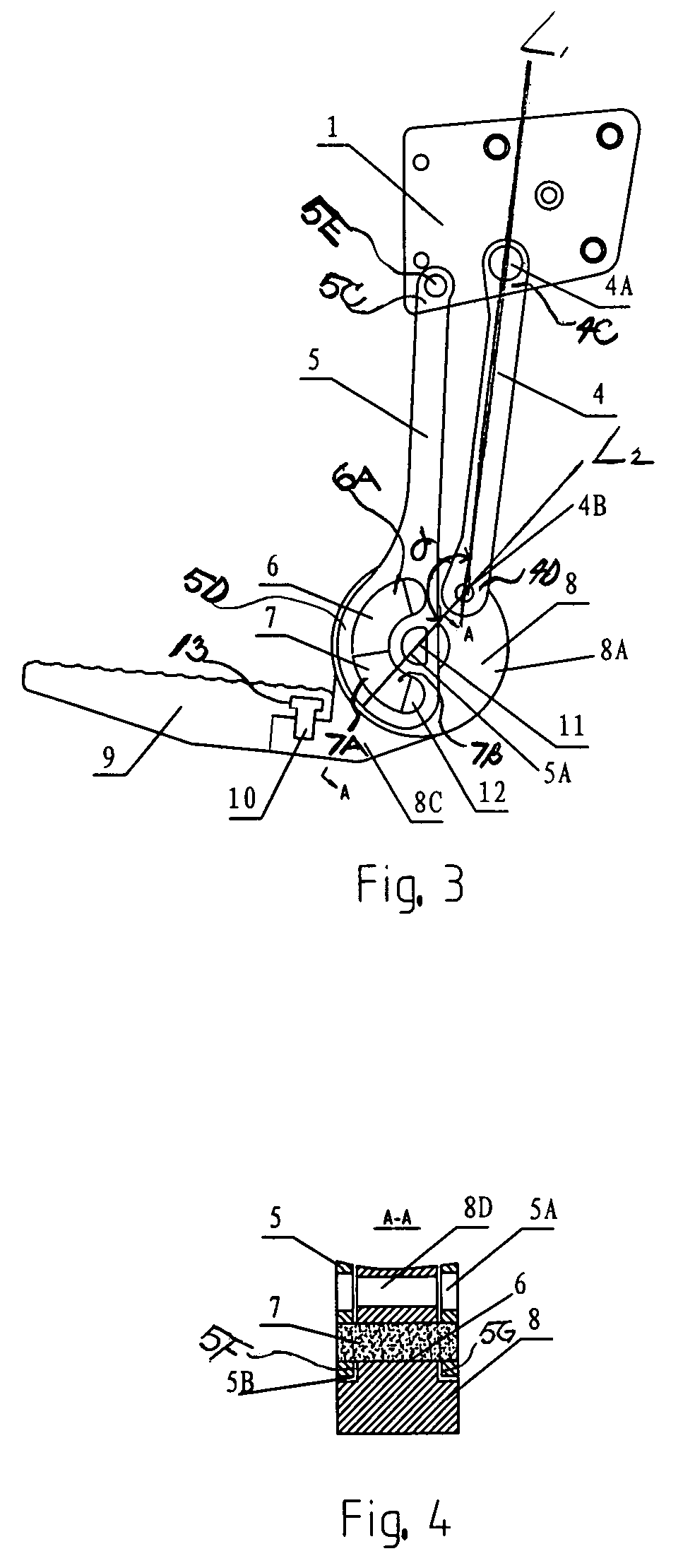
[0052]With reference to FIGS. 5-6 and 11, the device of the present invention will now be described. In general, this embodiment of the device includes a mounting bracket 1 adapted to be fixed to a body of a vehicle (not shown), a step bracket 8, an arc sliding member 7, a driving arm 4, and a supporting arm 5.

[0053]More specifically, the step bracket 8 includes a body portion 8A and an extension portion 8C extending from a lower part of the body portion 8A, and a vehicle step 9 is connected to and mounted on the extension portion 8C. The body portion 8A is formed with at least one arc slot 6.

[0054]A pair of ends 4C, 4D of the driving arm 4 are pivotally connected to the mounting bracket 1 and the body portion 8A of the step bracket 8, respectively, via, for example, corresponding pivot shafts 4A, 4B. An upper end portion 5C of the supporting arm 5 is pivotally connected to the mounting bracket 1 via a pivot shaft 5E.

[0055]The arc sliding member 7 is mounted to a lower end portion 5...


PUM


Abstract

An extending and retracting device for a vehicle step includes a mounting bracket adapted to be fixed to a body of a vehicle and a step bracket. An arc sliding member is fixed to the step bracket. A driving arm defines a pair of ends thereof pivotally connected to the mounting bracket and step bracket, respectively. A supporting arm defines an upper end portion thereof pivotally connected to the mounting bracket and a lower end portion of the supporting arm defining at least one arc slot of the lower end portion. The arc sliding member is adapted to fit into the arc slot so as to be slidable in the arc slot such that the lower end portion of the supporting arm is slidably connected to the step bracket.

Description

BACKGROUND OF THE INVENTION[0001]1. Field of the Invention[0002]The present invention relates, generally, to a vehicle body and, more particularly, to an extending and retracting device for a step of the vehicle body.[0003]2. Description of the Related Art[0004]With improvement of living standards, there are increased demands for comfortability of vehicles, such as cars. The step under a door of a vehicle is the only way to get on or off the vehicle. However, it is difficult to meet the trafficability and convenience requirements simultaneously when mounting the vehicle step. Considering trafficability of the vehicle, the level of the vehicle step should be higher than the ground clearance of the vehicle. In terms of ergonomics, the vehicle step is generally mounted at a level of 15 cm with respect to the ground so that it is convenient for a passenger of the vehicle to get on or off it, but this level cannot meet the trafficability requirements of most vehicles.[0005]In view of thi...

Claims


Application Information

Patent Timeline
Patent Type & Authority Patents(United States)
IPC IPC(8): B60R3/00
CPCB60R3/02
Inventor YANG, HUIZHONGQING, ZHAOBO
Owner HANGZHOU TIANMING TECH CO LTD
Why Eureka
Try Eureka