
Generalized pulse width modulation technique for specific inter-harmonics control of the inverters

a pulse width modulation and inverter technology, applied in the direction of optics, instruments, and harmonic reduction arrangements, can solve the problems of difficult to meet the requirements of response speed in the control system, the total modulation period needs relative too long time, etc., and achieve the effect of quick and accurate suppression of specific sub-harmonics

Active Publication Date: 2020-09-10
WUHAN UNIV
View PDF0 Cites 2 Cited by
  • Summary
  • Abstract
  • Description
  • Claims
  • Application Information

AI Technical Summary

Benefits of technology

The patent text describes a technique called PSR-PWM that can quickly and accurately reduce certain harmonic frequencies in power grids. This technique can help to reduce the unwanted movements of electricity in these grids and also damp out the oscillations caused by high-frequency levels.

Problems solved by technology

Further, when the desired frequency spectrum offset is large, using one fundamental period as one sub-cycle of modulation are not so effective because the voltage amplitude modulation degree is relatively low and the components of the remaining parasitic frequency are relatively high, meanwhile, the total modulation period needs relative too long time, it is difficult for meeting the requirements of response speed in a control system.

Method used


Image

  • Generalized pulse width modulation technique for specific inter-harmonics control of the inverters
  • Generalized pulse width modulation technique for specific inter-harmonics control of the inverters
  • Generalized pulse width modulation technique for specific inter-harmonics control of the inverters

Examples


Embodiment Construction

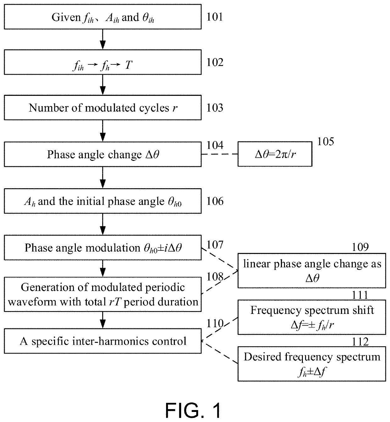
[0043]FIG. 1 is the schematic diagram of flow chart of specific inter-harmonics PWM control, where the symbol subscript ih represents the inter-harmonics parameter, the symbol subscript h represents the harmonic parameter, f represents the frequency, A represents the amplitude, θ represents the harmonic phase angle, Δθ represents the phase angle increment, and i is the modulation cycles index. The left part is the frequency, amplitude, and phase angle information of the given inter-harmonics; the nearest adjacent characteristic harmonics are selected as participating modulation harmonics and determining the relevant spectrum offset to determine the total number of fundamental wave sub-cycles r.

[0044](1) In 101, given a specific inter-harmonic with the information as frequency fih, amplitude Aih and phase θih;

[0045](2) In 102,103,104,105, selected the characteristic harmonic frequency fh that is nearest adjacent to the desired fih, determine the way of phase angle modulation, clockwi...


PUM

PropertyMeasurementUnit
frequencyaaaaaaaaaa
inter-harmonic frequencyaaaaaaaaaa

Abstract

This disclosure provides a PSR-PWM technique for high power active front-end inverters to damp a specific inter-harmonic that may cause relative sub-synchronous resonance in power system. Due to the strong interaction between wind power converters, photovoltaic converters, FACTS devices and HVDC transmission, low-frequency oscillations occur from a few Hz to dozens of Hz, or even high-frequency oscillations ranging from about 300-2000 Hz. Meanwhile, low-frequency oscillations ranging from 0.6 Hz to 7 Hz occur in the power supply systems of many electric locomotives. Even in the case of large-scale train outage, low-frequency oscillation will lead to abnormal locomotive dispatching system; in addition, the power grid voltage disturbance and flicker caused by a large number of high-power are furnaces and other nonlinear loads in the industrial field with a passband inter-harmonic frequency ranging from 0.05 Hz-90 Hz and so on are detected.

Description

CROSS-REFERENCE TO RELATED APPLICATION[0001]This application claims the priority benefit of China application serial no. 201910168261.7, filed on Mar. 6, 2019. The entirety of the above-mentioned patent application is hereby incorporated by reference herein and made a part of this specification.BACKGROUNDTechnical Field[0002]The invention relates to the field of inter-harmonic detection and suppression in power systems, in particular the selective control of amplitude and phase of inter-harmonics based on phase modulation.Description of Related Art[0003]The existing research of PWM technology applied in high-power inverter mainly carries out on harmonics. Harmonic current compensation control can be summarized into two types: non-selective harmonic compensation and selective harmonic compensation. Non-selective harmonic compensation means that the harmonic compensation command of the current controller is derived from the residual harmonic extracted from the fundamental wave. The se...

Claims


Application Information

Patent Timeline
Patent Type & Authority Applications(United States)
IPC IPC(8): G02F1/37H03K7/08
CPCG02F1/37H03K7/08Y02E40/40
Inventor ZHANG, HUIHE, YIGANGLIU, KAIPEIGUO, YUZHENGCHENG, YONGGUANGXIE, JIEXU, LEIZHOU, JINTAOGE, YUANZHELI, QIZHEN
Owner WUHAN UNIV
Learn More