Display panel and display device

Inactive Publication Date: 2020-09-17
SHARP KK
View PDF0 Cites 0 Cited by
  • Summary
  • Abstract
  • Description
  • Claims
  • Application Information

AI Technical Summary

Benefits of technology

[0019]According to one embodiment of the present invention, smooth display of a shape of a peripheral portion of a display region can be achie

Problems solved by technology

However, it is the case with the liquid crystal display device described in JP 5112961B that smooth display is not invariably achieved at the curved line portion, such as in a situation where the entir

Method used


Image

  • Display panel and display device
  • Display panel and display device
  • Display panel and display device

Examples


first embodiment

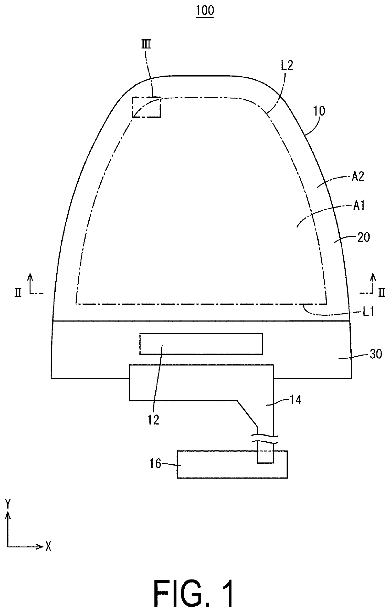
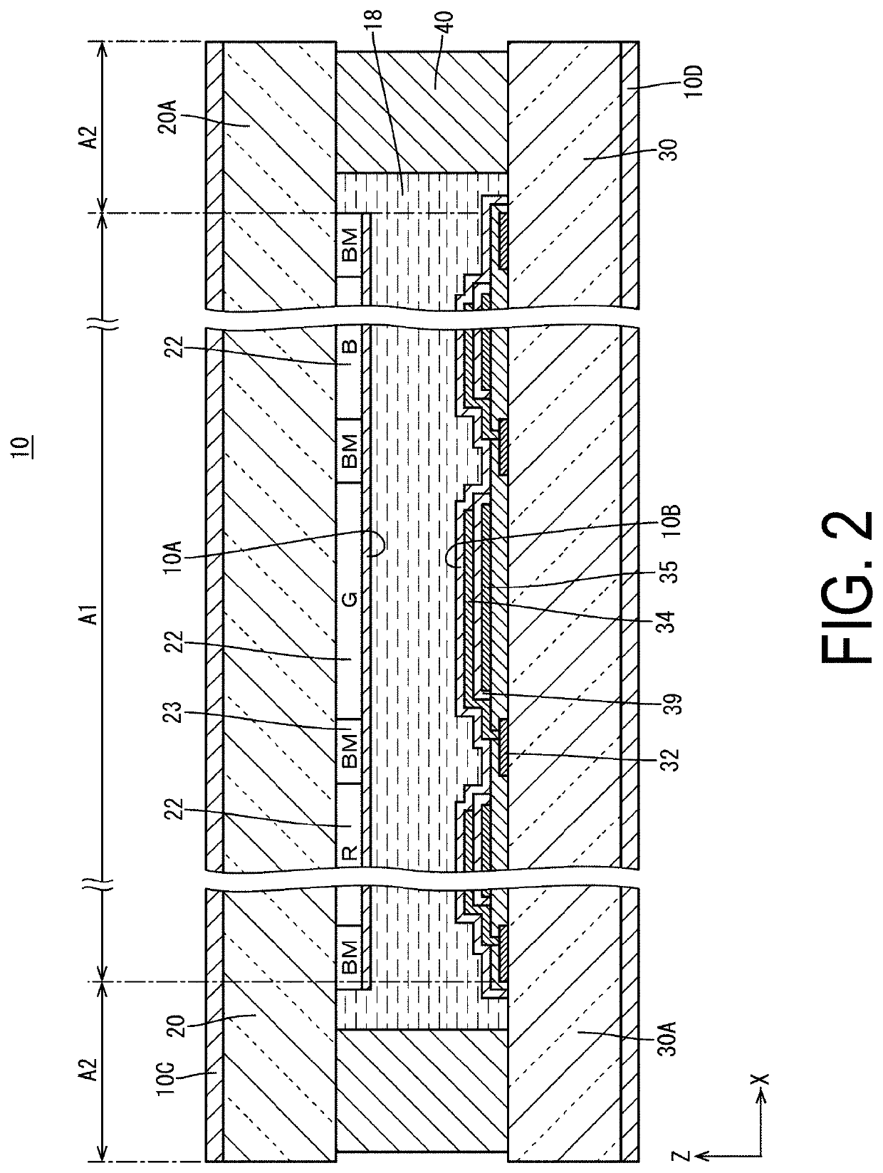
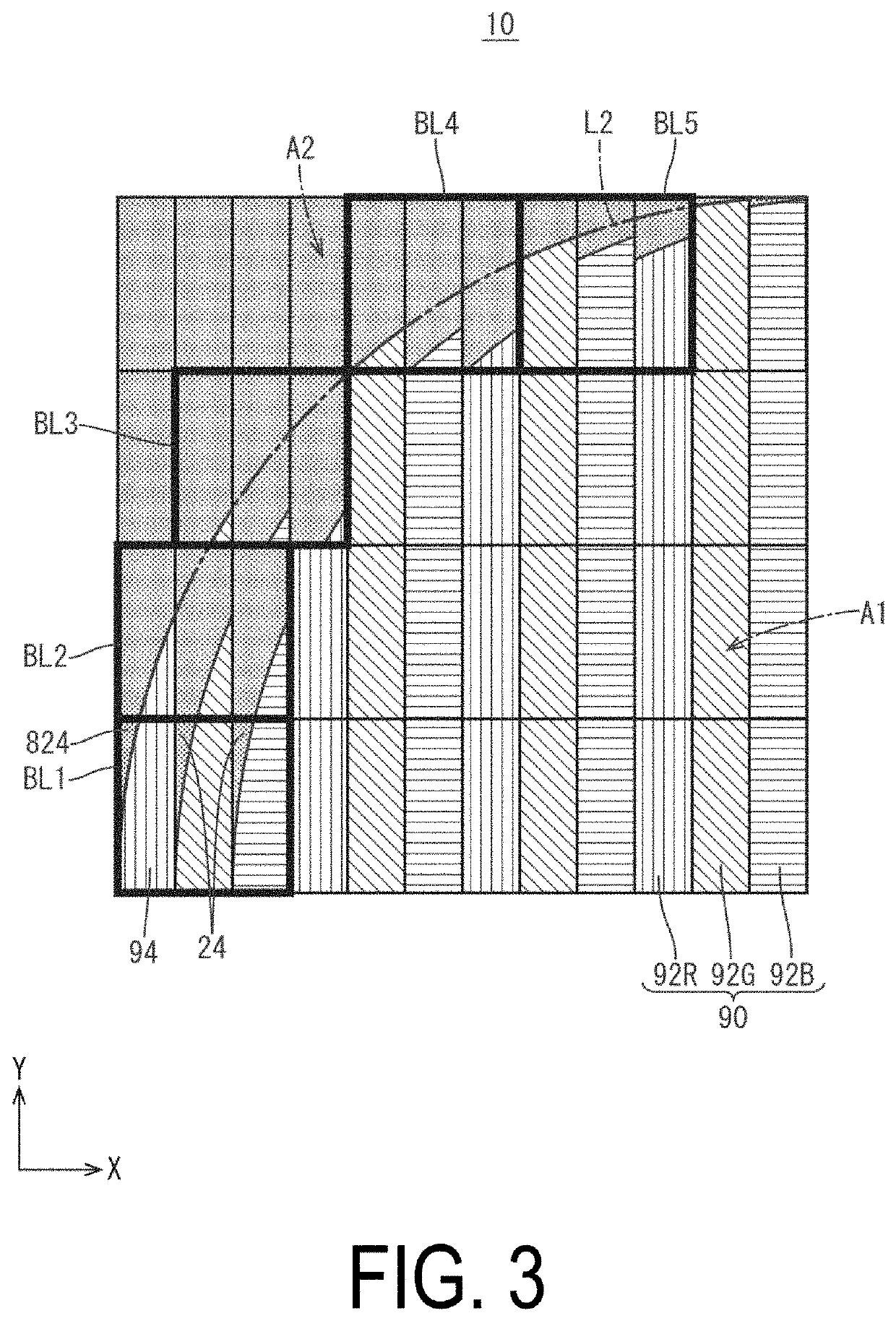
[0025]A first embodiment of the present invention will be described with reference to FIG. 1 to FIG. 3. The present embodiment exemplifies a liquid crystal display device 100 including a liquid crystal panel 10. Note that the X axis, the Y axis, and the Z axis are illustrated in a part of the drawings, and each axial direction is illustrated to be a common direction in each drawing. The +Z-axis direction (liquid crystal panel 10 side) herein represents the front side of the liquid crystal display device 100, and its opposite side (−Z-axis direction) represents the back side.

[0026]As illustrated in FIG. 1, the liquid crystal display device 100 (one example of a display device) includes the liquid crystal panel 10 (one example of a display panel) whose outer shape in a plan view includes a curved line portion, and an illumination device that is disposed on the back side of the liquid crystal panel 10 and emits light to be used for display to the liquid crystal panel 10. The central po...


PUM


Abstract

Display pixel includes colored pixels of n colors. In a case where a colored pixel being one of the colored pixels including the curved line portion and being located at an outermost end side in an array direction is defined as a display end pixel, the array direction being a direction in which the colored pixels are repeatedly arrayed with the colored pixels of the n colors being a unit, a first light blocking portion is provided in line with a shape of the curved line portion in the display end pixel, and a second light blocking portion having a shape and a size substantially the same as a shape and a size of the first light blocking portion is provided in each of the colored pixels of (n−1) colors consecutively arrayed next to the display end pixel toward the display region in the array direction.

Description

TECHNICAL FIELD[0001]The present invention relates to a display panel and a display device.BACKGROUND ART[0002]Liquid crystal display devices whose shape of a display region is formed into a non-rectangular shape, such as a circular shape, have hitherto been known. In such a liquid crystal display device, pixels located at a boundary portion between a display region of a curved shape and a non-display region include both a display region and a non-display region. Therefore, there are problems that smooth display cannot be achieved at the curved line portion, and the color balance is liable to be lost due to occurrence of coloring of a specific color in the pixels located at the boundary portion.[0003]To solve such problems, in a liquid crystal display device described in JP 5112961B, pixels located at the boundary portion of the curved line portion are classified into three types (a normal picture element, an aperture ratio adjustment picture element, and a non-lighting picture elem...

Claims


Application Information

Patent Timeline
IPC IPC(8): G02F1/1335G09G3/36
CPCG02F2201/52G02F1/133512G02F2001/133388G02F2201/56G09G2300/0443G09G3/3611G02F1/133514G09G2300/0426G09G2300/0452G02F1/133388
Inventor OHASHI, NORIYUKIKUROE, YASUHIRO
Owner SHARP KK
Why Eureka
Try Eureka