
Dummy hard disk drive

a hard disk drive and hdd technology, applied in the direction of record information storage, coupling device connection, instruments, etc., can solve the problems of not much financial margin in manufacturing and selling servers constructed from hdds, the hard disk drive industry is getting ever increasing pressure from solid state drives (ssds), and the manufacturers that use hard disk drives in their servers are running out of space on lower price or extracting profit from server systems, etc., to achieve the effect of reducing the number of chips

Active Publication Date: 2020-09-17
SPECTRA LOGIC
View PDF0 Cites 1 Cited by
  • Summary
  • Abstract
  • Description
  • Claims
  • Application Information

AI Technical Summary

Benefits of technology

The present invention is about a server box that contains multiple dummy hard drives (HDDs) which are in the server box. These dummy HDDs share a common set of components with a master components module. These fake HDDs are incomplete because they lack some of the necessary parts to function correctly. The master components module fills in the missing parts to make the dummy HDDs functional. This way, multiple dummy HDDs can be used in a server without needing a separate chipset for each one, which can save money and make the server more cost-effective. The master components module can also be designed to engage with a specific dummy HDD to complete it and store or retrieve data for the client or end user.

Problems solved by technology

Furthermore, the disk drive industry is getting ever increasing pressure from solid state drives (SSDs).
Accordingly, manufacturers that use hard disk drives (HDDs) in their servers are running out of room on lower price or extracting profit from server system.
In other words, there is not much financial margin today in manufacturing and selling servers constructed from HDDs.

Method used


Image

  • Dummy hard disk drive
  • Dummy hard disk drive
  • Dummy hard disk drive

Examples


embodiment 150

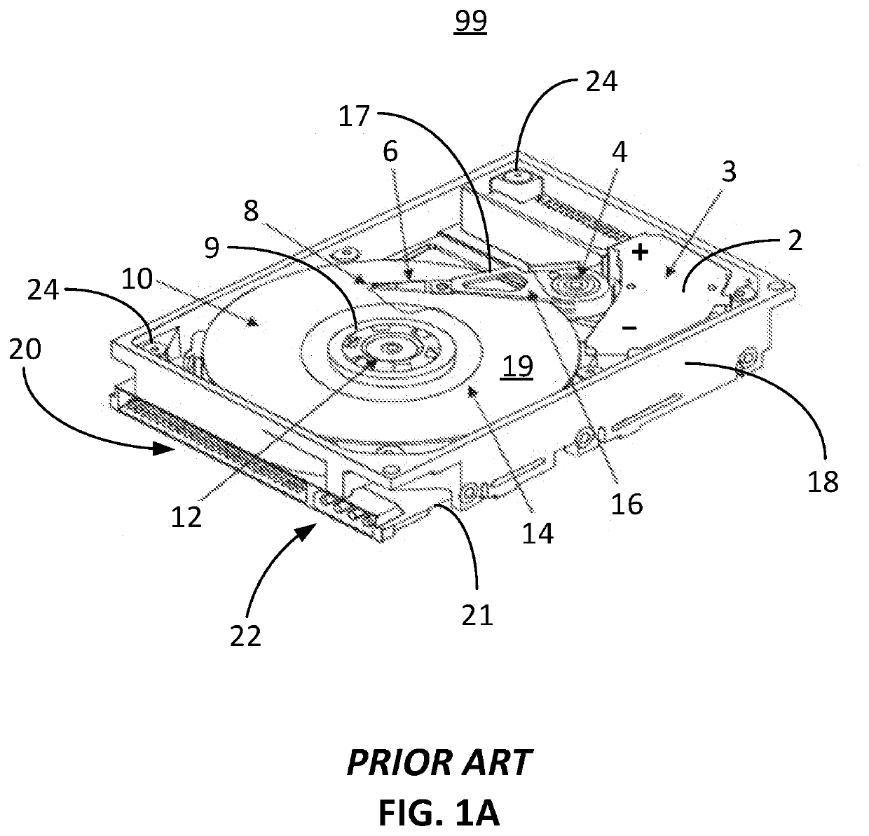
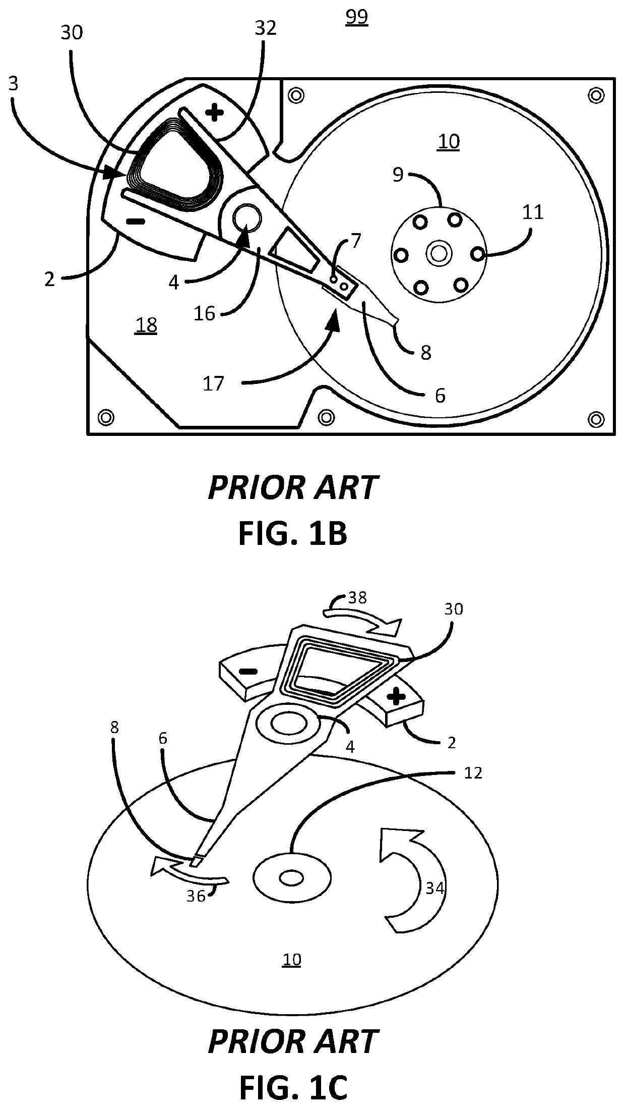
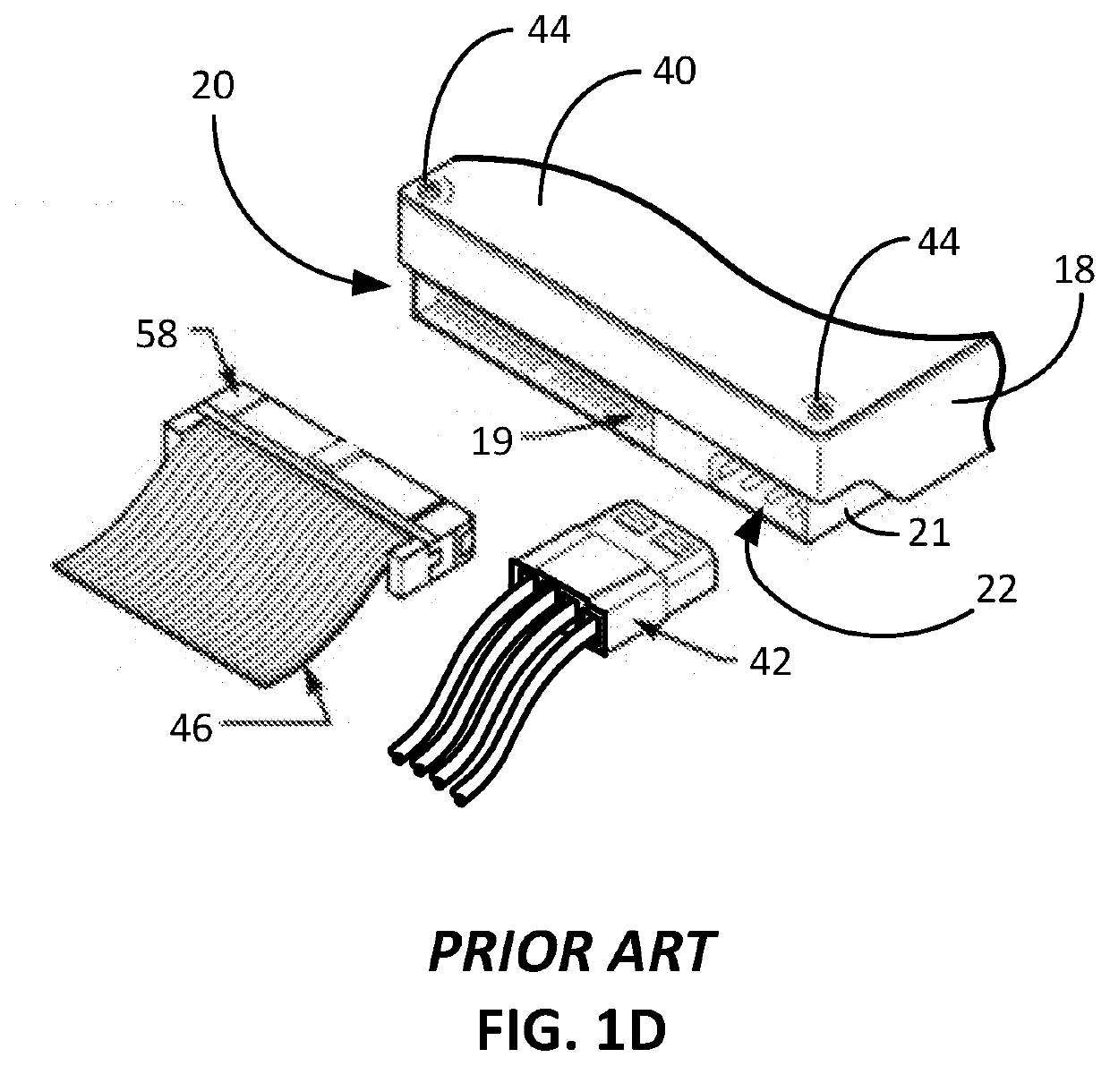
[0035]FIGS. 3A and 3B illustratively depict a dummy HDD embodiment 150 consistent with embodiments of the present invention. FIG. 3A illustratively depicts a front view of the dummy HDD 150 (the case / cover) roughly geometrically defined by a front surface 206, a back surface 208, left and right sides 204, a top side 202 and a bottom side 205. In this embodiment, the dummy PCB 210 comprises a connector tab 225 extending from the bottom side 205, as shown. The connector tab 225 comprises a plurality of electrical connector pads 220 viewable from only the front surface 206. Other embodiments envision the electrical connector pads 220 viewable from only the back surface 208. In the present embodiment, each of the electrical connector pads 220 corresponds to a connector pin 19 from the communications cable connection 20 and power pins 22 from a standard HDD 99. Of course, a skilled artisan will appreciate that the electrical connector pads 220 need only facilitate power to the dummy HDD ...

embodiment 100

[0042]Certain embodiments envision one or more ICs (chipsets) that are normally on a standard HDD PCB 60, e.g., spindle motor controller IC chips (that controls the speed of the spindle motor to a tightly controlled rpm, i.e., 6400 rpm+ / −0.2%), read channel IC chips, amplifiers, RAM chips, EEPROM's, etc., being either on the power module 410 or elsewhere so long as the one or more ICs are not residing locally on the dummy HDD 150. Certain other embodiments envision transmitting the functionality of these ICs through the power module 410 whereby some or none of these ICs are actually located on the power module 410. Accordingly, the controlling functions of a normal HDD 99 that typically resides on the PCB 60 are located externally from the dummy HDD 150 and shared between multiple dummy HDDs 150 in order to save more money. In this way, and in reference to the present server embodiment 100, four chipsets can be shared between one hundred and forty dummy HDDs 150 thereby saving the c...


PUM

PropertyMeasurementUnit
diameteraaaaaaaaaa
HDD perimeteraaaaaaaaaa
poweraaaaaaaaaa

Abstract

A server box embodiment is disclosed that generally comprises an array of dummy HDDs that share a common set of universal disk drive components in a master components module, or power module. Each dummy HDDs is constructed without expensive onboard chipsets that control the normal functionality of a standard HDD. By sharing expensive chipsets in a master components module (power module) money can be saved in building and selling the dummy HDD server. Embodiments envision a power module possessing the needed chipset functionality that is missing in a dummy HDD. The power module can be made to move from dummy HDD to dummy HDD supplying the necessary chipset in a shared manner when data is being stored or retrieved for client or end-user.

Description

CROSS-REFERENCE TO RELATED APPLICATIONS[0001]This application is a continuation of and claims priority to U.S. patent application Ser. No. 16 / 820,646, entitled SHARED DISK DRIVE COMPONENT SYSTEM filed Mar. 16, 2020, which in turn claims priority to and the benefit of U.S. Provisional Patent Application Ser. No. 62 / 818,325, entitled SHARED DISK DRIVE COMPONENT SYSTEM filed Mar. 14, 2019, the entire disclosure of which is hereby incorporated by reference.BACKGROUND OF THE INVENTION1. Field of the Invention[0002]The present invention relates generally to shared drive components used with multiple disk drives in an array of disk drives.2. Description of Related Art[0003]The disk drive industry is becoming commoditized with the leveling off of data storage capacity and the rate at which data is extracted or sent for storage. Furthermore, the disk drive industry is getting ever increasing pressure from solid state drives (SSDs). Accordingly, manufacturers that use hard disk drives (HDDs) ...

Claims


Application Information

Patent Timeline
Patent Type & Authority Applications(United States)
IPC IPC(8): G11B19/28G11B5/265G06F3/06
CPCG06F3/0679G06F3/0625G06F3/0658G11B19/28G11B5/2655H01R12/714H01R2201/06H05K1/117G11B5/012H05K2201/10159H05K2201/1009H05K2201/10204G11B33/0466G11B33/126G11B23/0318G11B19/209G06F3/0676G06F9/44505B65G47/90G11B19/08H01R13/24H01R13/642H05K1/111H05K1/181H05K7/1489H05K2201/10189
Inventor NESPECA, NICHOLAS ALDOBENSON, JONNEISEN, STEPHEN P.NINESLING, MATT JOHN
Owner SPECTRA LOGIC
Learn More