Calibration method for robot arm and calibration device thereof

a technology of robot arms and calibration devices, which is applied in the direction of programmed manipulators, instruments, programme control, etc., can solve the problems of low accuracy of calibration device installation, easy wear of measuring boards, and robot arms that do not know the real position of tool modules, so as to reduce manufacturing costs, speed and reliability of calibration process, the effect of improving efficiency

Active Publication Date: 2020-09-24
DELTA ELECTRONICS INC
View PDF0 Cites 1 Cited by
  • Summary
  • Abstract
  • Description
  • Claims
  • Application Information

AI Technical Summary

Benefits of technology

[0019]Utilizing the calibration method of the embodiment, the calibration process can be completed automatically. The speed and the reliability of the calibration process is improves. The efficiency is increased, and the manufacturing cost is decreased.

Problems solved by technology

When a tool module is installed at the end of a robot arm, the robot arm does not know the real position of the tool module.
The tool center point calibration is performed through contact calibration devices, which has the following risks: (1) the accuracy of the calibration device installation is low; (2) the measuring board wears easily; and (3) the aging of the return spring.
These factors may reduce the accuracy of the tool center point (TCP) calibration.

Method used


Image

  • Calibration method for robot arm and calibration device thereof
  • Calibration method for robot arm and calibration device thereof
  • Calibration method for robot arm and calibration device thereof

Examples


Embodiment Construction

[0032]The following description is of the best-contemplated mode of carrying out the invention. This description is made for the purpose of illustrating the general principles of the invention and should not be taken in a limiting sense. The scope of the invention is best determined by reference to the appended claims.

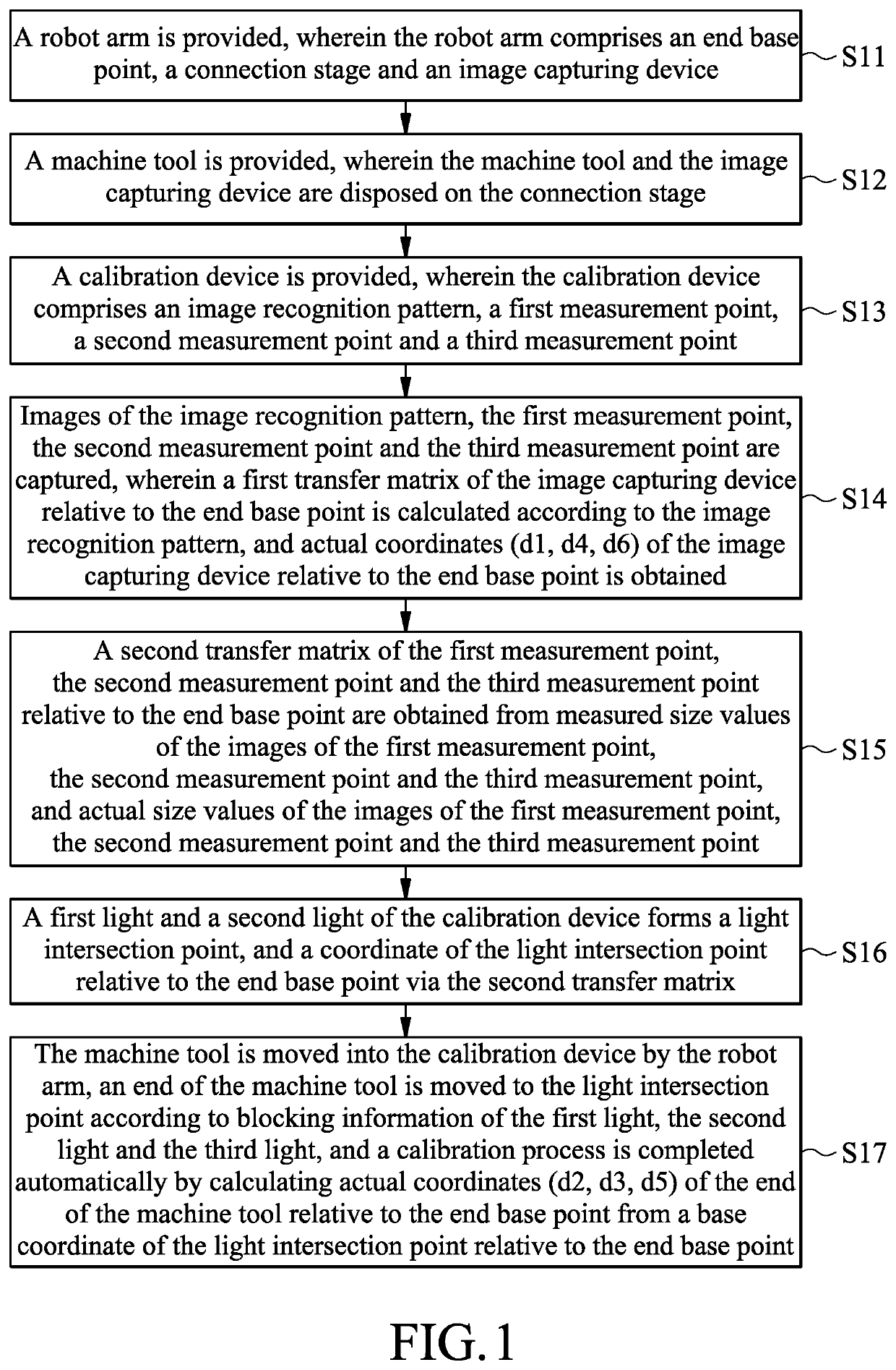
[0033]FIG. 1 shows a flow chart of a calibration method of an embodiment of the invention. The calibration method includes the following steps. First, a robot arm is provided, wherein the robot arm comprises an end point of reference, a connection stage and an image capturing device (S11). Then, a machine tool is provided, wherein the machine tool and the image capturing device are disposed on the connection stage (S12). Next, a calibration device is provided, wherein the calibration device comprises an image recognition pattern, a first measurement point, a second measurement point and a third measurement point (S13). Then, images of the image recognition pattern, the...


PUM


Abstract

A calibration device is provided. The calibration device includes a frame, a first optical sensing device, a second optical sensing device and a third optical sensing device. The frame includes a bottom plate and at least four sidewalls, wherein the sidewalls have a first grating hole, a second grating hole, a third grating hole and a fourth grating hole at a first height. The bottom plate has an image recognition pattern, a first measurement point, a second measurement point and a third measurement point.

Description

CROSS REFERENCE TO RELATED APPLICATIONS[0001]This Application claims priority of China Patent Application No. 201910212670.2, filed on Mar. 20, 2019, the entirety of which is incorporated by reference herein.BACKGROUND OF THE INVENTIONField of the Invention[0002]The present invention relates to a calibration method for a robot arm and a calibration device thereof, and in particular to an automatic calibration method and a calibration device thereof.Description of the Related Art[0003]In recent years, robotic arms have been widely used in the manufacturing industry. The end of a robotic arm may be equipped with tool modules to perform the required tasks, such as a drilling tool module, a gripping tool module, or a grinding tool module. These tool modules may also be used with a vision system module. When a tool module is installed at the end of a robot arm, the robot arm does not know the real position of the tool module. The offset relationship between the tool center point (TCP) an...

Claims


Application Information

Patent Timeline
Patent Type & Authority Applications(United States)
IPC IPC(8): B25J9/16B25J19/00
CPCB25J9/1697B25J9/1692B25J19/0095G05B2219/39045G05B2219/39024G01B21/042G05B2219/39057G05B2219/39016G05B2219/39025
Inventor HSIAO, YUAN-KUNLAI, JIAN-JANGCHEN, KO-YUEH
Owner DELTA ELECTRONICS INC
Why Eureka
Try Eureka