Stator vane of fan or compressor

Active Publication Date: 2020-09-24
IHI CORP
View PDF0 Cites 0 Cited by
  • Summary
  • Abstract
  • Description
  • Claims
  • Application Information

AI Technical Summary

Benefits of technology

The patent text describes a problem in the design of stator vanes for fans or compressors. The flow of air around the blade surface decelerates as it flows through the inter-blade flow channel, causing a rapid transition from a laminar to a turbulent boundary layer. This results in high friction and low efficiency. The patent aims to solve this problem by controlling the sharpness of the decrease in the blade surface angle, which delays the transition of the boundary layer and increases the laminar flow area, reducing friction and loss.

Problems solved by technology

However, in the turbulent boundary layer, the velocity gradient of the flow near the wall surface is great, so that the frictional stress is high.

Method used


Image

  • Stator vane of fan or compressor
  • Stator vane of fan or compressor
  • Stator vane of fan or compressor

Examples


Embodiment Construction

[0038]In the following, an embodiment of the present disclosure will be described in detail with reference to the drawings.

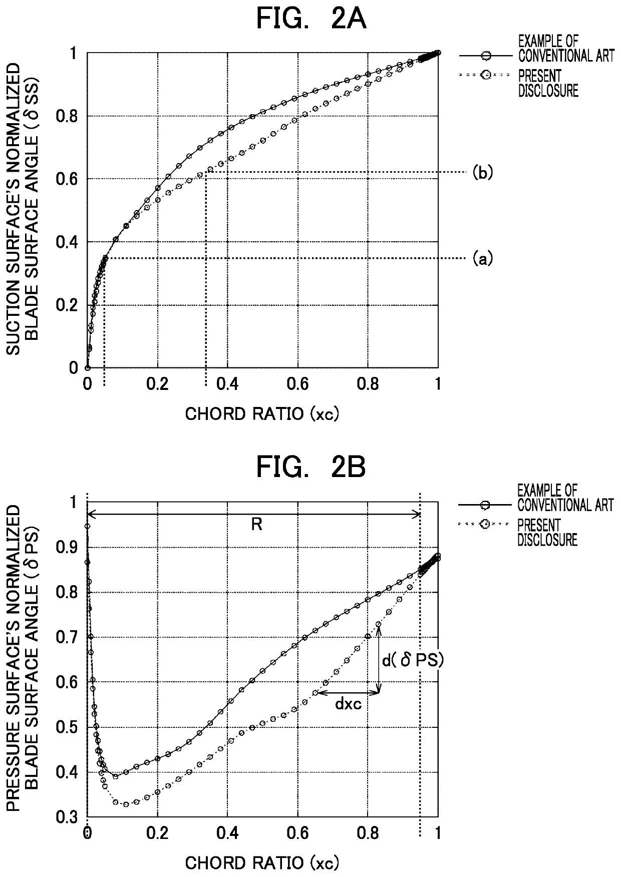
[0039]With the conventional stator vane, a sharp deceleration of the flow occurs in a region where a chord ratio is from about 0.20 to 0.35 on the suction surface. This means that the suction surface's blade surface angle sharply decreases or, in other words, the suction surface's normalized blade surface angle sharply increases in the region. The chord ratio (xc), which is a non-dimensional value, is the distance (x) from the leading edge measured in the chord direction divided by the chord length (c).

[0040]For the pressure surface, also with the conventional stator vane, the change rate of the pressure surface's blade surface angle preferably has an upper limit in order to maintain a boundary layer over the blade surface in a laminar state.

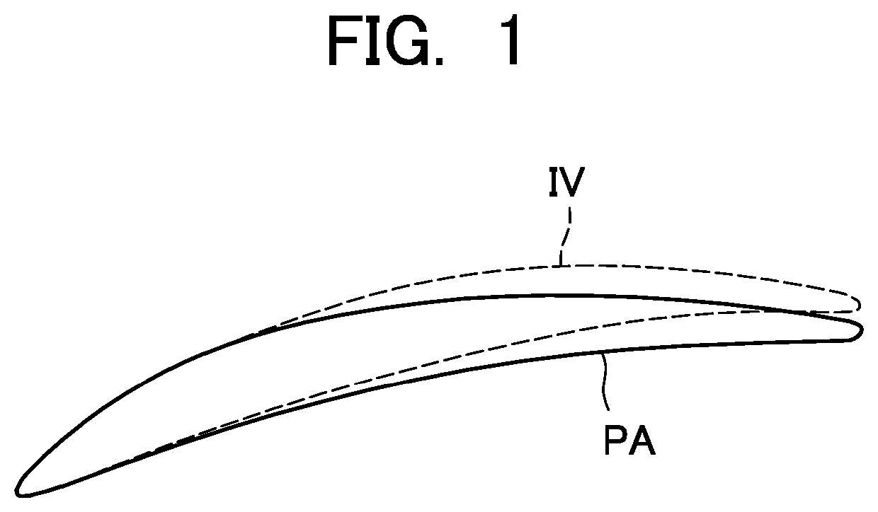
[0041]In view of this, a stator vane according to the embodiment of the present disclosure has an airfoil obtained by modi...


PUM


Abstract

To provide a stator vane of a fan or compressor that is reduced in loss by enlarging a laminar flow area over a blade surface. With the stator vane, provided that an angle formed by a tangent to the blade surface at a point and the axial direction of the turbofan engine, that is, a parameter that is a blade surface angle normalized is referred to as a normalized blade surface angle, an upper limit is set for the change rate in the chord direction of the normalized blade surface angle on the pressure surface, and an upper limit is set for the normalized blade surface angle at a predetermined location in the chord direction on the suction surface.

Description

TECHNICAL FIELD[0001]The present disclosure relates to a stator vane of a fan or compressor that is a component of a turbofan engine. In particular, it relates to a stator vane of a fan or compressor that is reduced in loss by controlling deceleration of a flow around the blade and enlarging a laminar flow area over the blade surface.BACKGROUND ART[0002]A fan or compressor that is a component of a turbofan engine is provided with a rotor blade and a stator vane. FIG. 3 shows a stator vane as an example of the stator vane. Note that the terms “radial direction”, “circumferential direction” and “axial direction” used in the following description coincide with the radial direction, the circumferential direction and the axial direction of a turbofan engine incorporating the stator vane, respectively.[0003]FIG. 3 is a schematic perspective view of a stator vane SV. The stator vane SV includes a blade part AF, and an outer band OB and an inner band IB. The blade part AF is a part that ext...

Claims


Application Information

Patent Timeline
IPC IPC(8): F01D9/02
CPCF05D2240/122F01D9/02F05D2240/124F02C7/00F04D19/02F04D29/54F01D9/041F05D2220/36F05D2220/3216F01D5/145F01D5/141F05D2210/34F05D2270/17F05D2240/123F05D2240/121
Inventor HAYASHI, RYOSUKEOKADA, RYUICHIMUROOKA, TAKESHIENOKI, TOMONORI
Owner IHI CORP
Why Eureka
Try Eureka