Planetary gear train of internal engagement type

Active Publication Date: 2016-03-24
DENSO CORP
View PDF5 Cites 1 Cited by
  • Summary
  • Abstract
  • Description
  • Claims
  • Application Information

AI Technical Summary

Benefits of technology

[0022]Accordingly, a friction loss can be reduced, because the possible contact between the tooth-front portions of the external and the internal gears can be avoided when the external gear tooth and the internal gear tooth are located in the teeth non-engagement region. As a result, it becomes possible to prevent a decrease of torque transmission efficiency.
[0023]In addition, it becomes possible to make larger a clearance in a radial dire

Problems solved by technology

According to the planetary gear train of the internal engagement type disclosed in the above prior art, however, it is not always possible to prevent a possible contact between the top portion of the gear tooth of the internal gear and the top portion of the gear tooth of the ex

Method used


Image

  • Planetary gear train of internal engagement type
  • Planetary gear train of internal engagement type
  • Planetary gear train of internal engagement type

Examples


Example

First Embodiment

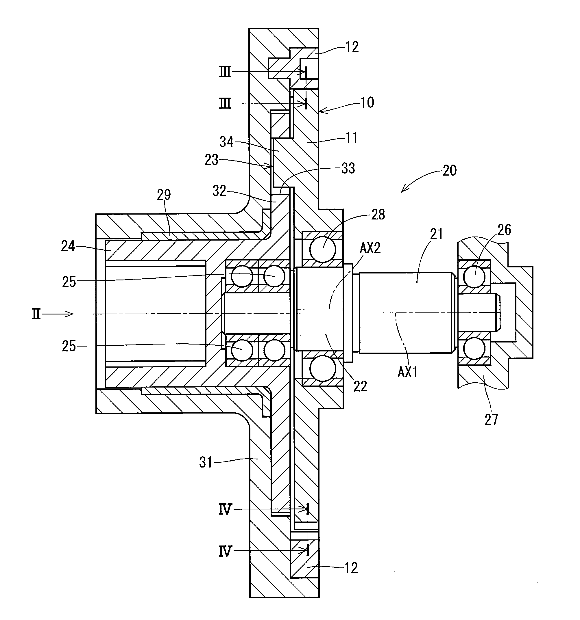
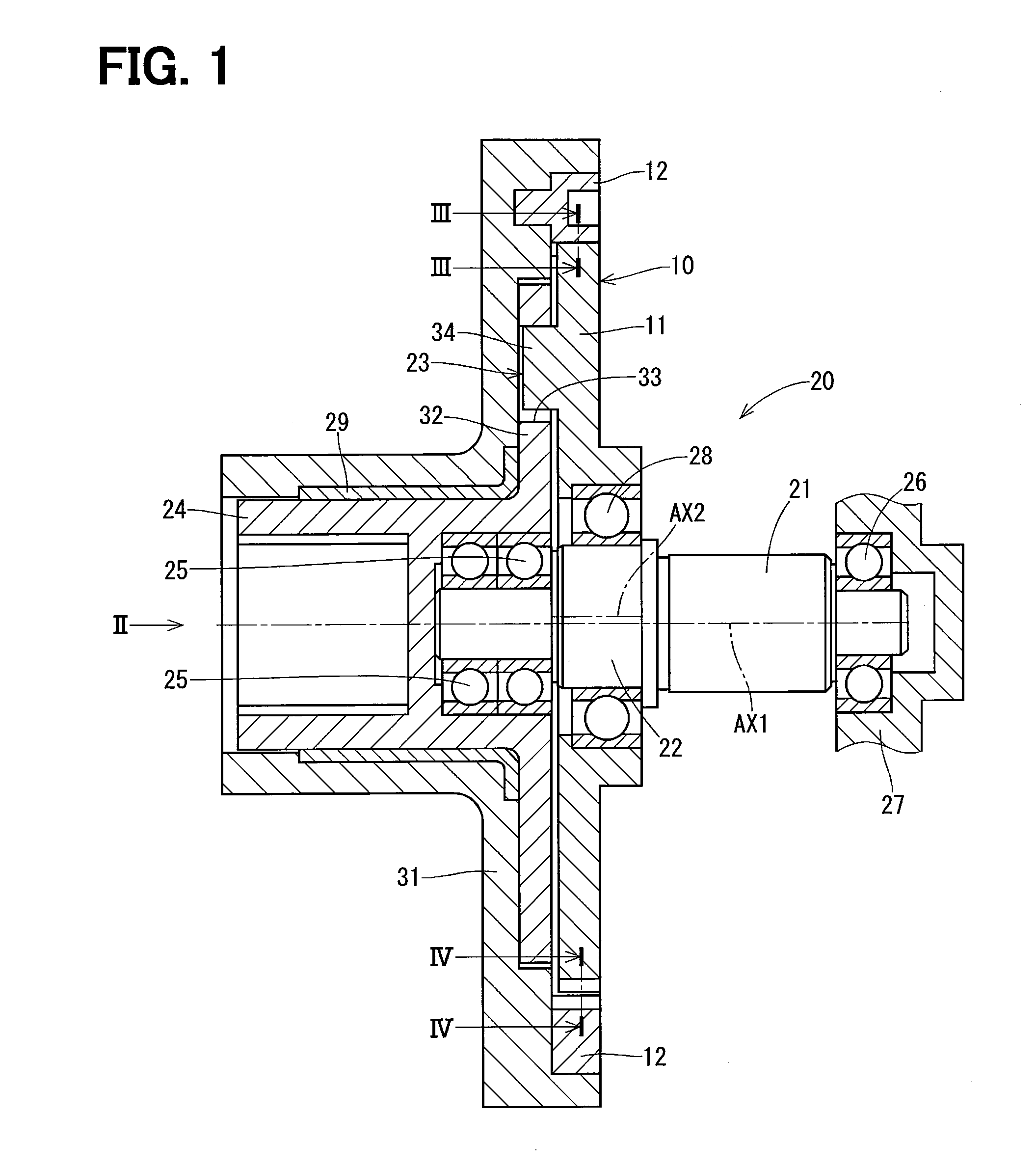
[0039]A speed decreasing device 20 of a first embodiment of the present disclosure is shown in FIG. 1, to which a planetary gear train 10 of an internal engagement type is applied. For example, the speed decreasing device 20 is installed in a vehicle in order to decrease a rotational speed of an electric motor, which is a driving portion for a shift-by-wire system.

(Structure of Speed Decreasing Device)

[0040]At first, a structure of the speed decreasing device 20 will be explained with reference to FIGS. 1 and 2.

[0041]The speed decreasing device 20 is composed of (but not limited thereto);

[0042]a first shaft 21;

[0043]an eccentric portion 22 formed in the first shaft 21;

[0044]an external gear 11 supported by the first shaft 21 via the eccentric portion 22, so that the external gear 11 is eccentrically rotated with respect a center axis AX1 of the first shaft 21;

[0045]an internal gear 12, with which the external gear 11 is internally engaged;

[0046]a transmission unit 23...

Example

Second Embodiment

[0111]Characterizing features of the planetary gear train of the internal engagement type according to a second embodiment of the present disclosure will be explained with reference to FIGS. 7 to 10.

[0112]As shown in FIGS. 7 and 8, an outer peripheral portion of an external gear 41 has multiple external gear teeth, each of which is composed of the tooth-bottom portion 13, the tooth-middle portion 14 and a tooth-front portion 42. A transverse cross-sectional shape of the tooth-front portion 42 of the external gear 41 is formed by an epicycloid curved line.

[0113]An inner peripheral portion of an internal gear 43 has multiple internal gear teeth, each of which is composed of the tooth-bottom portion 16, the tooth-middle portion 17 and a tooth-front portion 44.

[0114]A transverse cross-sectional shape of the tooth-front portion 44 of the internal gear 43 is formed by a second predetermined curved line (a second tooth-front curved line for the internal gear 43), which is ...

Example

Third Embodiment

[0157]Characterizing features of the planetary gear train of the internal engagement type according to a third embodiment will be explained with reference to FIGS. 11 to 12.

[0158]As shown in FIGS. 11 and 12, each of the tooth-front portions 15 and 44 of the external gear 11 and the internal gear 43 has a runout portion. More exactly, in the same manner to the first embodiment, the first runout portion is formed in the external gear 11 in such a way that the tooth-front portion 15 of the external gear 11 is escaped in the radial-inward direction from the reference epicycloid curved line “CLEPI”. In addition, in the same manner to the second embodiment, the second runout portion is formed in the internal gear 43 in such a way that the tooth-front portion 44 of the internal gear 43 is escaped in the radial-outward direction from the reference hypocycloid curved line “CLHYPO”.


PUM


Abstract

Each of gear teeth of an external gear has a tooth-bottom portion, a tooth-middle portion and a tooth-front portion. The tooth-middle portion is operatively engaged with an internal gear. A cross-sectional shape of the tooth-bottom portion is formed by a hypocycloid curved line. A cross-sectional shape of the tooth-middle portion is formed by an epicycloid curved line. A cross-sectional shape of the tooth-front portion is formed by a first predetermined curved line, which is located at a position closer to a first pitch circle of the external gear in a radial-inward direction from a reference epicycloid curved line. The reference epicycloid curved line is continuously connected to each of the curved lines of the tooth-middle portion at both circumferential sides of each gear tooth. As a result, the tooth-front portion is so formed that a part of the tooth-front portion is escaped in the radial-inward direction from the reference epicycloid curved line.

Description

CROSS REFERENCE TO RELATED APPLICATION[0001]This application is based on Japanese Patent Application No. 2014-193881 filed on Sep. 24, 2014, the disclosure of which is incorporated herein by reference.FIELD OF TECHNOLOGY[0002]The present disclosure relates to a planetary gear train of an internal engagement type.BACKGROUND[0003]A planetary gear train of an internal engagement type is known in the art. For example, the planetary gear train of the internal engagement type is used in a speed decreasing device, a speed increasing device and so on. The planetary gear train of the internal engagement type has an internal gear and an external gear, which is internally engaged with the internal gear.[0004]In each of an internal gear and an external gear for a planetary gear train of an internal engagement type, which is disclosed in Japanese Patent No. 4,107,895, a runout portion is formed at a bottom portion of a gear tooth. A possible contact between the bottom portion of the internal gea...

Claims


Application Information

Patent Timeline
IPC IPC(8): F16H1/32
CPCF16H2001/327F16H1/32F16H55/08F16H2001/325F16H2055/0893
Inventor TABUCHI, TORUNAKAYAMA, SEIJI
Owner DENSO CORP
Why Eureka
Try Eureka