Clutch release device for a friction clutch of a motor vehicle with a fail-safe system

Inactive Publication Date: 2007-09-06
ZF FRIEDRICHSHAFEN AG
View PDF8 Cites 0 Cited by
  • Summary
  • Abstract
  • Description
  • Claims
  • Application Information

AI Technical Summary

Benefits of technology

[0011]To guarantee that the clutch-release device can continue to operate even under emergency conditions, it is advantageous for the first and second axial stops to arrive in a state of engagement with each other under the effect of axial load as soon as a defect which leads to a mutual axial displacement of the bearing rings of the clutch-release bearing occurs in the clutch-release bearing.
[0012]When the axial stops are a certain distance away from each other during normal operation and come to rest against each other when the bearing becomes defective, it is highly favorable for the first and the second axial stops to have surfaces which are optimized for sliding behavior and which form a friction bearing when a defect occurs. For this purpose, at least one of the sliding contact surfaces can be enhanced by a coating of plastic, for example, or by a metal coating known to the man of the art such as a coating of lead, tin, aluminum, or copper alloy. As a result of this measure, frictional losses can be reduced, and the emergency running properties of the clutch-release device are improved.

Problems solved by technology

As a result, the ball cage in the roller bearing is destroyed, since it is usually made of plastic, and the rolling elements can no longer be kept the proper distance apart.
This can cause the roller bearing to jam and lead to an undesirable axial displacement of the bearing rings with respect to each other.
In the worst case, the bearing rings can no longer be held together and, in the case of a clutch of the pulled type, the bearing ring in working connection with the release element can become separated axially from the other bearing ring, as a result of which the friction clutch can no longer be actuated.
This problem can also occur in the case of a clutch-release device of the pushed type.
Once a certain amount of axial displacement is exceeded, a clutch-release bearing of this type can also fail during operation.
In the worst case, a vehicle with a defective clutch-release device of this type can no longer move under its own power and must be towed, even though the drive train and the entire system for transmitting power to the drive wheels are still functional.

Method used


Image

  • Clutch release device for a friction clutch of a motor vehicle with a fail-safe system
  • Clutch release device for a friction clutch of a motor vehicle with a fail-safe system
  • Clutch release device for a friction clutch of a motor vehicle with a fail-safe system

Examples


Embodiment Construction

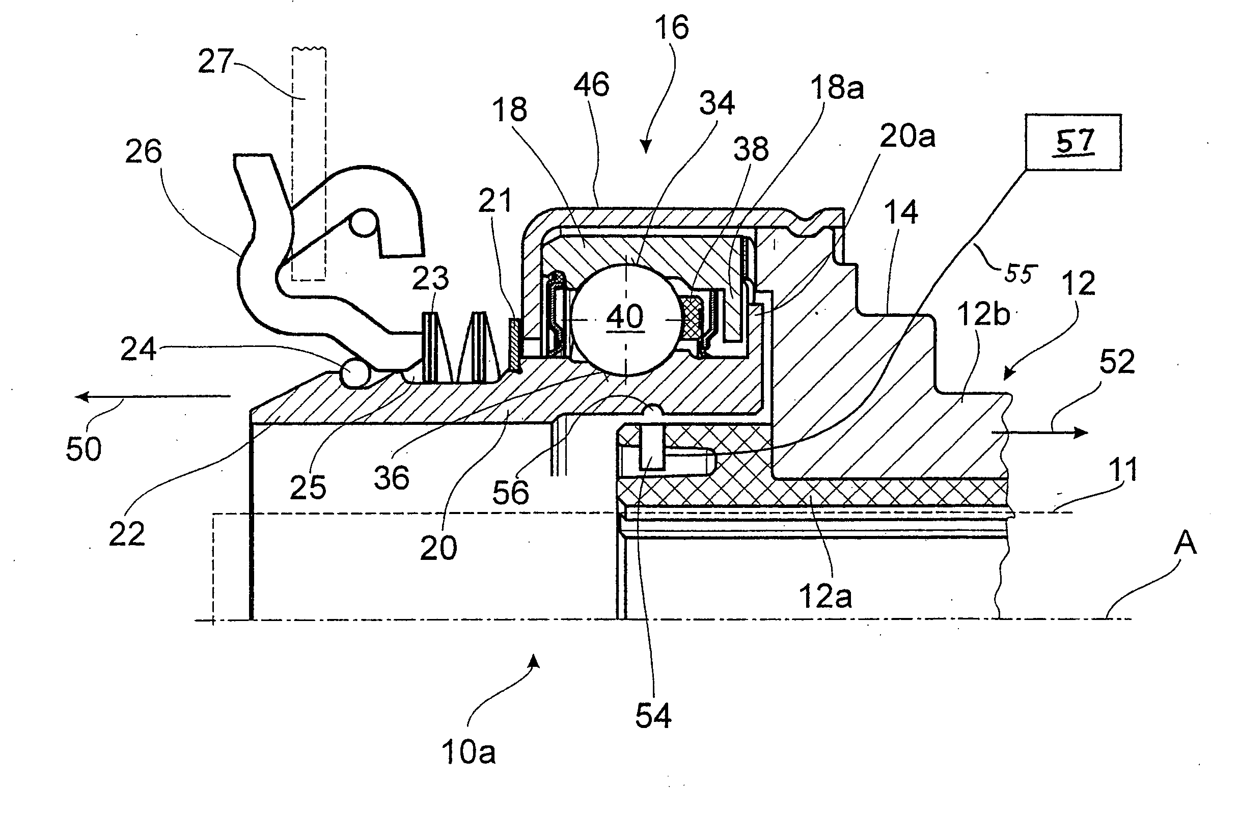
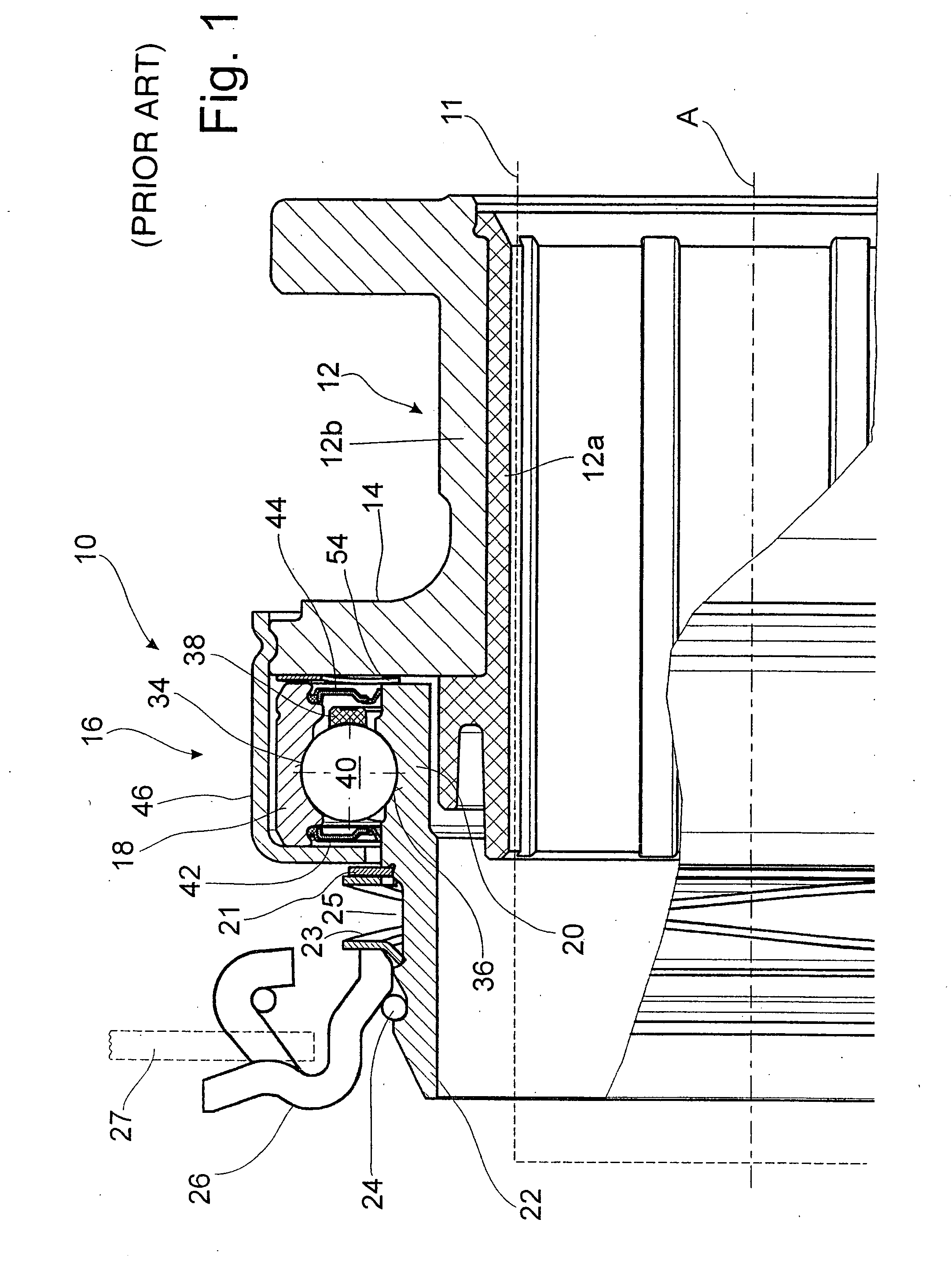
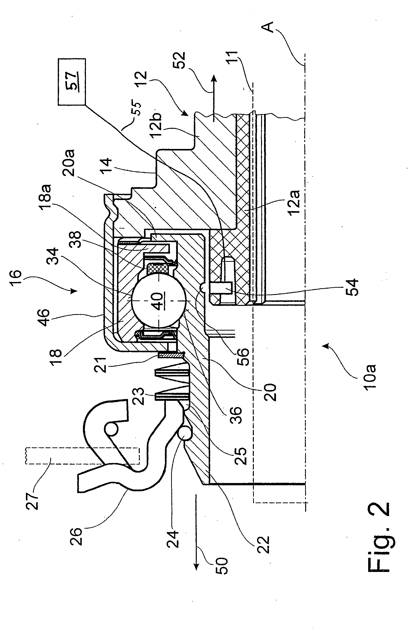
[0020]FIG. 1 shows a clutch-release device 10 of the pulled type for actuating a motor vehicle friction clutch (not shown in the drawing). The device includes a sliding sleeve 12, which is made up of two parts, namely, an inner part 12a and an outer part 12b. The sleeve is able to shift its position axially on a guide tube. The sleeve has a radial flange 14, to which is attached a clutch-release bearing 16, designed as an angular-contact ball bearing. The ball bearing 16 has a first, radially outer bearing ring 18, which is stationary with respect to the sliding sleeve 12, and a rotating second, radially inner bearing ring 20 with an axial extension 22 which extends beyond the bearing 16. The inner ring is in working connection by means of a load ring 24 and a release ring 26 with the ends of the tongues of a diaphragm spring 27 (only partially shown in the figure), which represents the release element of the friction clutch to be actuated. To guarantee that the release ring 26 rest...


PUM


Abstract

A clutch release device for the friction clutch of a motor vehicle includes a sliding sleeve which can shift position axially on a guide tube, and a roller bearing positioned on the sliding sleeve. The roller bearing includes a first bearing ring, which can rotate with a clutch release element, a second bearing ring, which is fixed against rotation relative to the sliding sleeve, and a plurality of rolling elements which roll on races in the bearing rings. In the event of bearing failure, first and second axial stops engage to prevent relative axial displacement of the bearing rings by more than a predetermined amount. The first axial stop is fixed with respect to the first bearing ring, and the second axial stop is axially fixed with respect to the sliding sleeve.

Description

BACKGROUND OF THE INVENTION[0001]1. Field of the Invention[0002]The present invention pertains to a clutch-release device including a sliding sleeve which can shift position axially on a guide tube, and a roller bearing positioned on the sliding sleeve, the roller bearing including a first bearing ring, which can rotate with a clutch release element, a second bearing ring, which is fixed against rotation relative to the sliding sleeve, and a plurality of rolling elements which roll on races in the bearing rings.[0003]2. Description of the Related Art[0004]Clutch-release devices of the general type in question for actuating the friction clutches of motor vehicles are sufficiently well known. See, for example, the devices disclosed in U.S. Pat. Nos. 5,295,566 and 5,836,432, both of which are of the “pulled” type. A clutch-release device can also be of the “pushed” type, as described, for example, in DE 101 36 424 C1. These types of clutch-release devices include, as their main compone...

Claims


Application Information

Patent Timeline
IPC IPC(8): F16D21/00
CPCF16D23/14
Inventor OTTO, THOMASVOIT, HERBERT
Owner ZF FRIEDRICHSHAFEN AG
Why Eureka
Try Eureka