Seal ring

Active Publication Date: 2018-04-12
RIKEN CO LTD
View PDF8 Cites 7 Cited by
  • Summary
  • Abstract
  • Description
  • Claims
  • Application Information

AI Technical Summary

Benefits of technology

The patent describes a seal ring that can reduce friction and oil leakage. This means that the seal ring can improve the performance and reliability of the device it is used in.

Problems solved by technology

During driving of the automatic transmission, a friction loss is caused between that seal ring and the shaft due to its rotation relative to the shaft.
Such a friction loss result in drive loss of the hydraulic machine.

Method used


Image

  • Seal ring
  • Seal ring
  • Seal ring

Examples


Embodiment Construction

[0045]Hereinafter, an embodiment of the present invention will be described with reference to the drawings.

1. Seal Ring 1

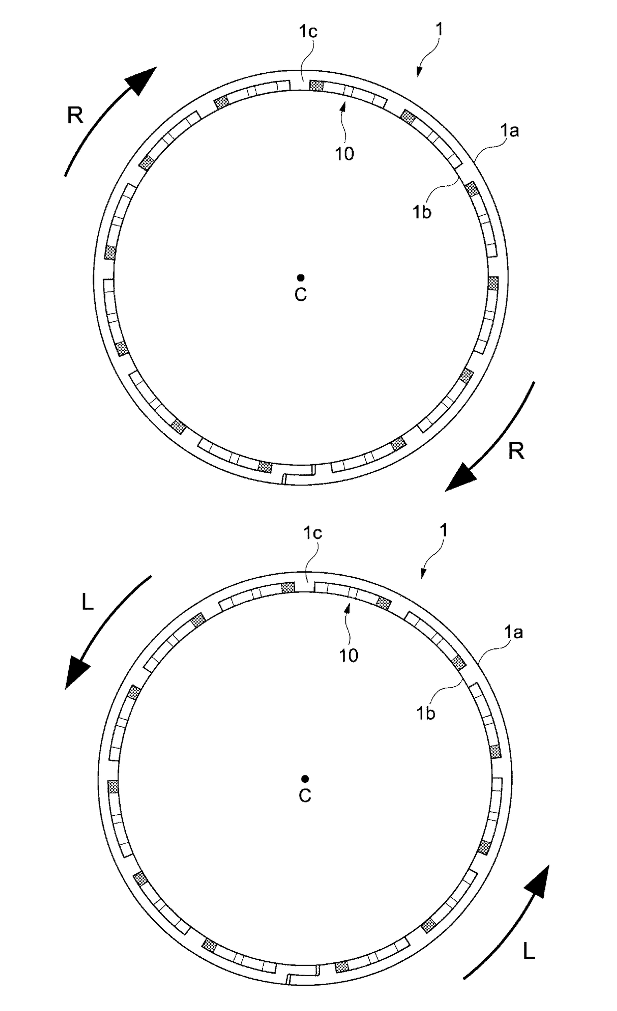
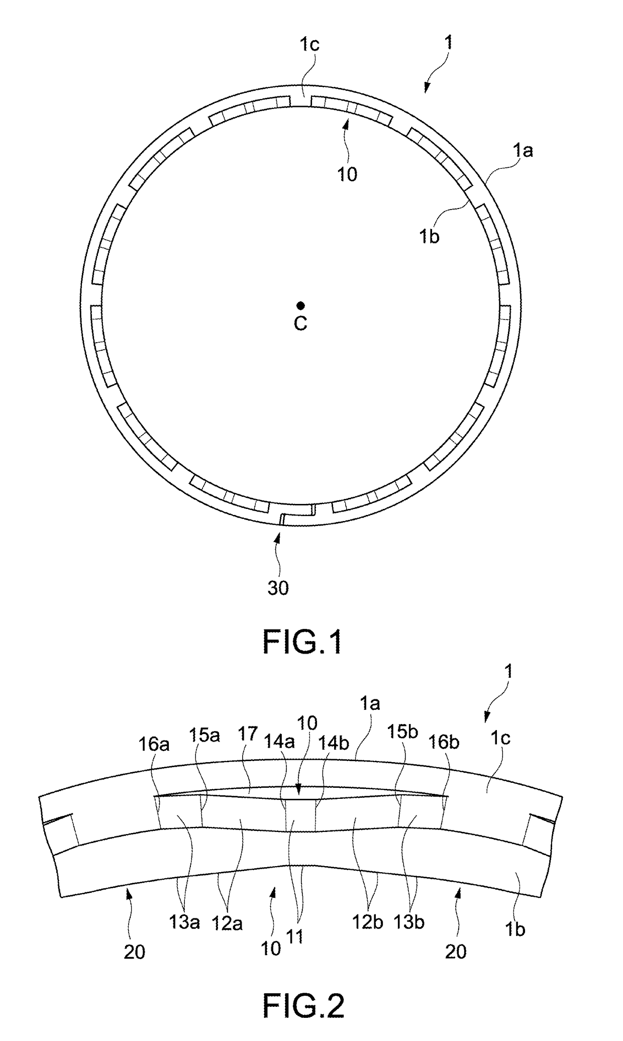
[0046]FIG. 1 is a plan view of a seal ring 1 according to an embodiment of the present invention. The seal ring 1 includes an outer circumferential surface 1a, an inner circumferential surface 1b, and side surfaces 1c. The seal ring 1 is formed in an annular shape having a central axis C as a center. The outer circumferential surface 1a and the inner circumferential surface 1b are cylindrical surfaces each having the central axis C as a center. The side surfaces 1c are flat surfaces orthogonal to the outer circumferential surface 1a and the inner circumferential surface 1b.

[0047]The seal ring 1 includes a plurality of pockets 10. The plurality of pockets 10 arranged in the two side surfaces 1c, spaced apart from one another. Each pocket 10 is formed in a concave shape recessed from the side surface 1c. Further, the seal ring 1 is provided with a joint portion 30 ...


PUM


Abstract

[Object] To provide a seal ring capable of both reducing a friction loss and reducing oil leakage.[Solving Means] A seal ring includes: an inner circumferential surface; an outer circumferential surface orthogonal to the inner circumferential surface; side surfaces orthogonal to the inner circumferential surface and the outer circumferential surface; and a plurality of pockets provided, spaced apart from one another in one of the side surfaces. The plurality of pockets each have a symmetrical shape in a circumferential direction and are opened on a side of the inner circumferential surface and closed on a side of the outer circumferential surface. The plurality of pockets each include circumferential end portions that are provided in end portions in the circumferential direction and are R-surfaces each having a convex shape connected to the side surface, a bottom portion provided in a central region in the circumferential direction, and inclined portions each extending between each of the circumferential end portions and the bottom portion. The inclined portions each include at least one ridge portion, a first inclined portion extending between the bottom portion and the ridge portion and forming a first angle with respect to the side surface, and a second inclined portion extending between the circumferential end portion and the ridge portion and forming a second angle smaller than the first angle with respect to the side surface.

Description

TECHNICAL FIELD[0001]The present invention relates to a seal ring that can be used for a hydraulic machine and the like.BACKGROUND ART[0002]There are known automobiles equipped with various hydraulic machines such as hydraulic-type automatic transmissions. In those automobiles, there is a demand for reduction in drive loss of the hydraulic machines so as to improve fuel efficiency.[0003]Seal rings are used for the hydraulic-type automatic transmissions. The seal ring is fitted into a groove of a shaft inserted into a housing, and seals a gap between the housing and the shaft. During driving of the automatic transmission, a friction loss is caused between that seal ring and the shaft due to its rotation relative to the shaft.[0004]Such a friction loss result in drive loss of the hydraulic machine. Therefore, a technology for reducing the friction loss is desirable. Patent Literatures 1 to 5 have disclosed technologies for reducing the friction loss caused between the seal ring and th...

Claims


Application Information

Patent Timeline
IPC IPC(8): F16J15/28
CPCF16J15/28F16J15/3272F16J15/3408F16J15/3412F16J15/18F16J15/182
Inventor PARK, NAMSUN
Owner RIKEN CO LTD
Why Eureka
Try Eureka