Bearing device for wheel

Inactive Publication Date: 2006-06-22
NTN CORP
View PDF5 Cites 6 Cited by
  • Summary
  • Abstract
  • Description
  • Claims
  • Application Information

AI Technical Summary

Benefits of technology

[0023] One embodiment of the present invention is a bearing apparatus for a wheel of vehicle comprising a hub wheel integrally formed therewith a wheel mounting flange on the periphery at one end thereof, and a double row rolling bearing, the double row rolling bearing comprising an outer member integrally formed therewith a body mounting flange on the periphery thereof and also formed therewith double row outer raceway surfaces, an inner member including said hub wheel and formed therewith double row inner raceway surfaces each arranged opposite to each of said double row outer surfaces, and double row rolling elements freely rotatably contained between said double row outer and second raceway surfaces, said double row rolling bearing being adapted to be applied a predetermined preload characterized in that: there are arranged a separate outer or inner ring on at least one of said outer and inner members, and a preload varying means arranged at an abutting portion between said outer and inner members for varying a preload applied to the bearing, said preload varying means can be extended or contracted based on an output signal from a detecting sensor for detecting the running condition of vehicle. This makes it possible to suppress the inclination of the brake rotor by increasing the bearing preload when the bearing rigidity is required during cornering of vehicle and thus to ensure safety driving without any irregular motion. On the contrary, when the vehicle is running on a straight road, it is possible to reduce the rotational torque and the friction loss of the bearing by reducing the bearing preload and thus to improve the fuel consumption.
[0024] Another embodiment of the present invention is a bearing apparatus for a wheel of vehicle comprising a hub wheel integrally formed therewith a wheel mounting flange on the periphery at one end thereof, and a double row rolling bearing, the double row rolling bearing comprising an outer member integrally formed therewith a body mounting flange on the periphery thereof and also formed therewith double row outer raceway surfaces, said hub wheel formed on its outer periphery with one of the inner raceway surfaces of the double row rolling bearing and with an axially extending cylindrical portion from the inner raceway surface, an inner member including a separate inner ring press fitted on the axially extending portion, and double row rolling elements freely rotatably contained between said double row outer and second raceway surfaces, said double row rolling bearing being adapted to be applied a predetermined preload characterized in that: said outer member comprises an outer ring member formed on its inner periphery with one of the outer raceway surfaces and a separate outer ring formed on its inner periphery with the other of the outer raceway surfaces, and an electrostrictive element arranged at an abutting portion between said outer ring member and the o

Problems solved by technology

Of course the bearing preload influences not only the bearing life, but the environmental problems such as safety driving and an improvement of fuel consumption

Method used


Image

  • Bearing device for wheel
  • Bearing device for wheel
  • Bearing device for wheel

Examples


first embodiment

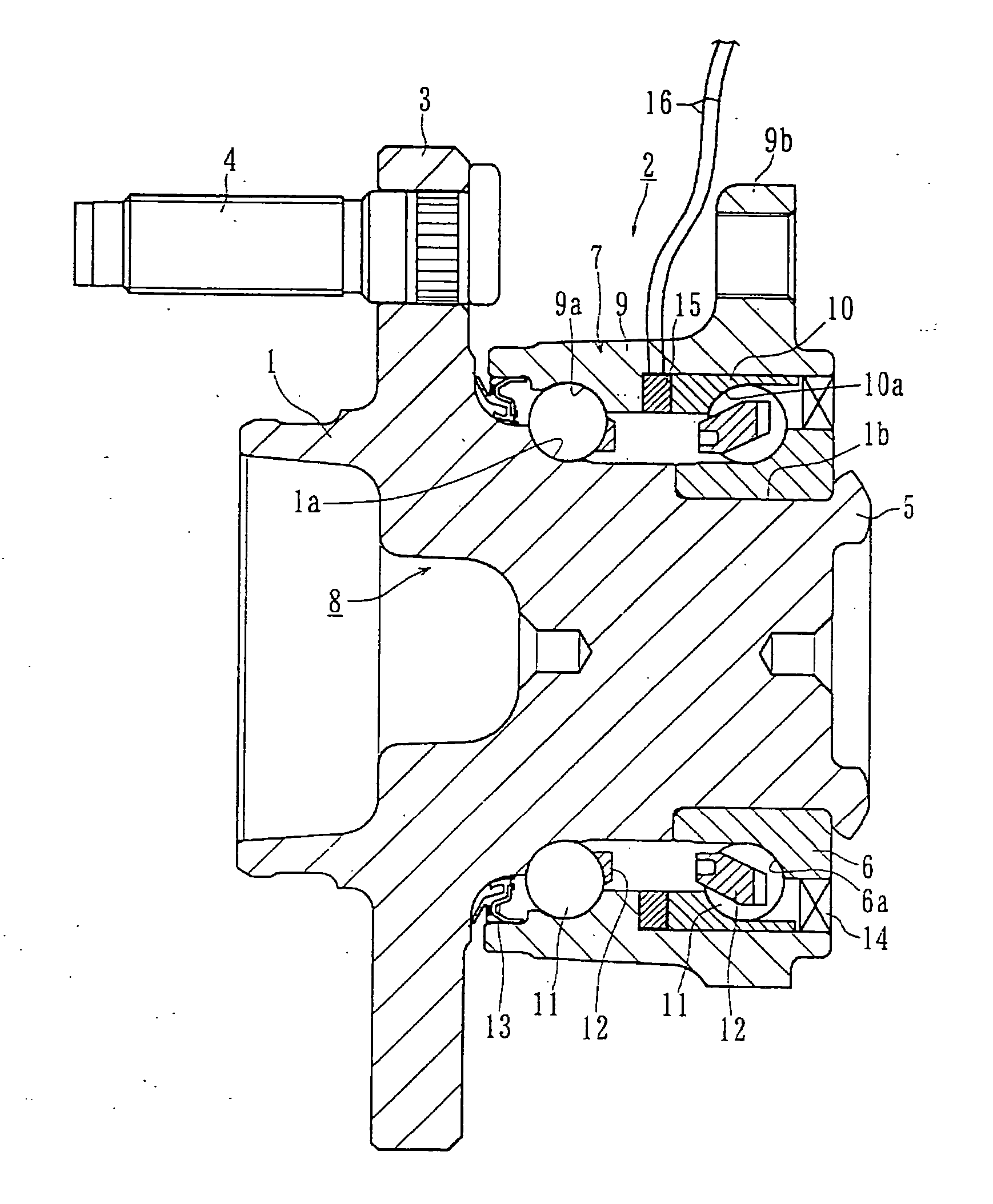
[0040] Preferred embodiments of the present invention will be described with reference to the accompanied drawings. FIG. 1 shows a first embodiment of a bearing apparatus for a wheel of vehicle of the present invention.

[0041] The bearing apparatus for a wheel of vehicle is that used for a driven wheel and comprises a hub wheel 1 and a double row rolling bearing 2. In the description below, a term “outboard side” (left hand side in drawings) of the apparatus denotes a side which is positioned outside of the vehicle body and a term “inboard side” (right hand side in drawings) of the apparatus denotes a side which is positioned inside of the body when the bearing apparatus is mounted on the vehicle body.

[0042] The hub wheel 1 is integrally formed with a wheel mounting flange 3 at an end of the outboard side, an outboard side inner raceway surface 1a of a double row rolling bearing 2 on the outer peripheral surface thereof, and a cylindrical portion 1b axially extending from the inner...

second embodiment

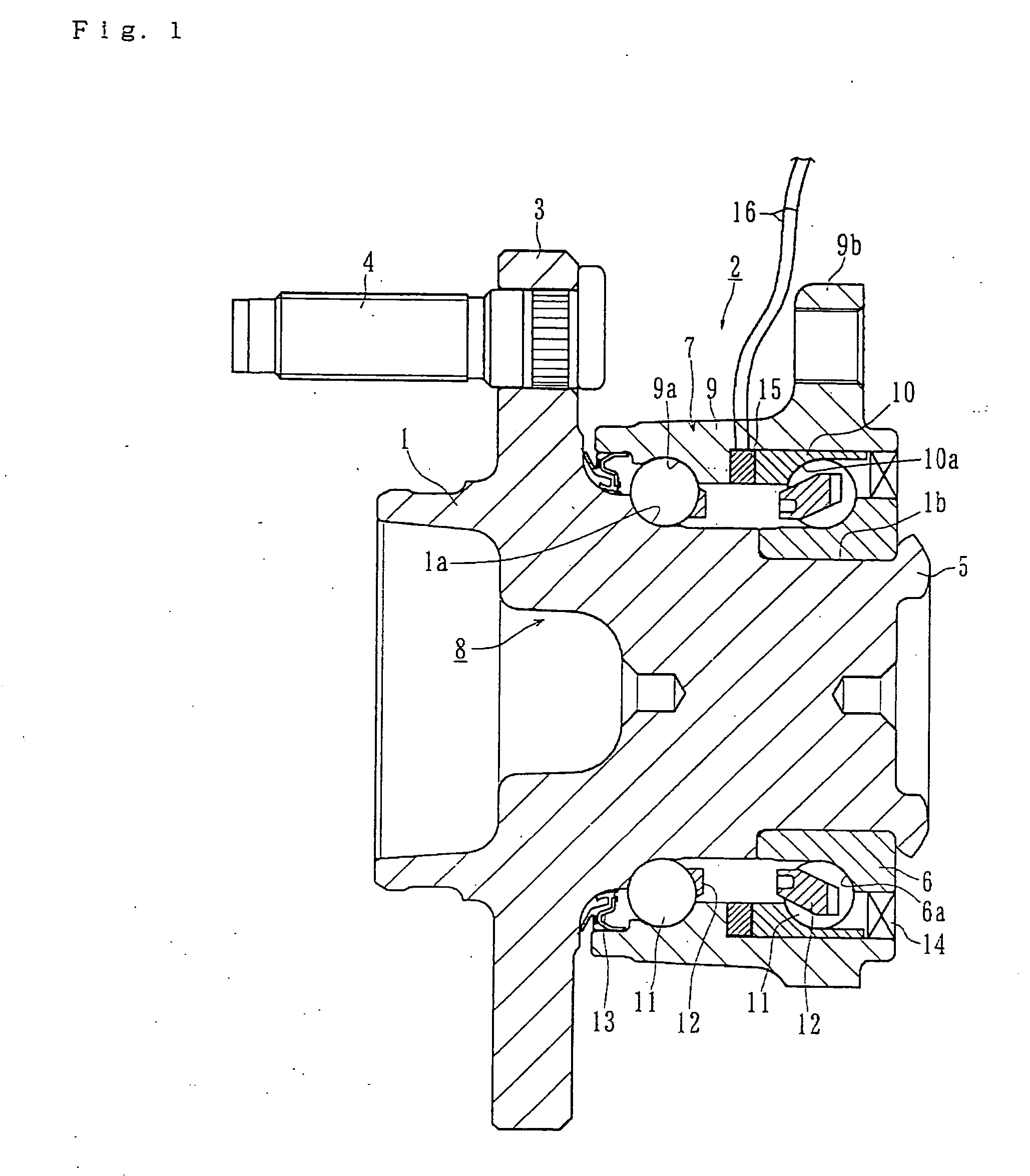
[0046]FIG. 2 is a longitudinal view showing a second embodiment of the bearing apparatus for a wheel of the present invention. Same reference numerals are used in this embodiment for designating same parts having same functions used in the first embodiment.

[0047] This bearing apparatus for a wheel of vehicle comprises the hub wheel 1 and a double row rolling bearing 17 and this double row rolling bearing 17 comprises an outer member 18, an inner member 19 and the double row rolling elements 11 and 11. The outer member 18 is integrally formed on its outer peripheral surface with a body mounting flange 9b for mounting the bearing apparatus on the body (not shown) of vehicle and on its inner peripheral surface double row outer raceway surfaces 9a and 9a.

[0048] A separate inner ring 6 is press fitted onto the axially extending portion 1b of the hub wheel 1 and secured thereto by the caulked portion 5. The double row rolling elements 11 and 11 are contained between the double row outer...

third embodiment

[0053]FIG. 4 is a longitudinal view showing a third embodiment of the bearing apparatus for a wheel of the present invention. Same reference numerals are used in this embodiment for designating same parts having same functions used in the second embodiment since this embodiment is different from the second embodiment only in its preload applying structure.

[0054] This bearing apparatus for a wheel of vehicle comprises a hub wheel 23 and a double row rolling bearing 24 and this double row rolling bearing 24 comprises an outer member 18, an inner member 25 and the double row rolling elements 11 and 11. The outer member 18 is integrally formed on its outer peripheral surface with a body mounting flange 9b for mounting the bearing apparatus on the body (not shown) of vehicle and on its inner peripheral surface double row outer raceway surfaces 9a and 9a. A separate inner ring 6 is press fitted onto the axially extending portion 1b of the hub wheel 23. The double row rolling elements 11 ...


PUM


Abstract

According to the present invention, there is provided a bearing apparatus for a wheel of vehicle comprising a hub wheel integrally formed therewith a wheel mounting flange on the periphery at one end thereof, and a double row rolling bearing, the double row rolling bearing comprising an outer member integrally formed therewith a body mounting flange on the periphery thereof and also formed therewith double row outer raceway surfaces, an inner member including said hub wheel and formed therewith double row inner raceway surfaces each arranged opposite to each of said double row outer surfaces, and double row rolling elements freely rotatably contained between said double row outer and second raceway surfaces, said double row rolling bearing being adapted to be applied a predetermined preload characterized in that: there are arranged a separate outer or inner ring on at least one of said outer and inner members, and a preload varying means arranged at an abutting portion between said outer and inner members for varying the preload applied to the bearing, said preload varying means can be extended or contracted based on an output signal from a detecting sensor for detecting the running condition of vehicle.

Description

BACKGROUND OF THE INVENTION [0001] 1. Field of the Invention [0002] The present invention relates to a bearing apparatus for a wheel of vehicle for rotatably supporting the wheel of vehicle such as an automobile, and more particularly to a bearing apparatus for a wheel of vehicle having a preload varying means built in the bearing apparatus for variably setting an optimum preload suitable for the running condition of vehicle. [0003] 2. Description of Background Art [0004] The power transmitting apparatus for transmitting an engine power to wheels is required not only to allow power transmission from an engine to wheels, but to allow radial and axial displacement from wheels as well as momentum displacement caused by bounds of body of vehicle during running on a rough road and cornering of vehicle. Accordingly, as shown in FIG. 12, one end of a driving shaft 100 arranged between an engine and a driving wheel is connected to a differential apparatus 102 via a sliding type constant vel...

Claims


Application Information

Patent Timeline
IPC IPC(8): F16C41/04F16C19/18B60B35/18F16C19/52F16C25/06F16C25/08F16C33/60F16C41/00
CPCF16C19/186F16C19/52F16C25/08F16C41/00
Inventor OKADA, KOICHIHAYASHI, YUTAKAIWAMOTO, KENICHIKOIKE, TAKASHI
Owner NTN CORP
Why Eureka
Try Eureka