Objective lens driver, method of manufacturing objective lens driver, optical pickup device and optical disk apparatus

a technology of optical pickup device and optical disk, which is applied in the direction of information storage, instruments, data recording, etc., can solve the problems of inability to obtain the required space for the connection of the flexible member to the focusing coil and the tracking coil, and the inability to narrow the gap between the top and bottom flexible members further

Inactive Publication Date: 2007-07-26
PANASONIC CORP
View PDF10 Cites 7 Cited by
  • Summary
  • Abstract
  • Description
  • Claims
  • Application Information

AI Technical Summary

Benefits of technology

[0010]To resolve these problems, one objective of the present invention is to provide a thin type of objective lens driver that can control the inclination of an objective lens relative to an optical disk, a method for manufacturing this objective lens driver, an optical pickup device and an optical disk apparatus.

Problems solved by technology

However, it becomes difficult for the gap between the top and bottom flexible members to be narrowed further when three rows of flexible members be arranged in the direction of the thicknesses at both ends of the lens holders.
That is, a problem has arisen in that the required space can not be obtained for the connection of the flexible members to the focusing coils and the tracking coils, and the connection of the flexible members to conductive lines to feed power to the focusing coils and the tracking coils.
As another problem, when the flexible members, the lens holder and the fixing members are to be integrally formed in order to reduce the gap between the individual flexible members, the thickness of the spacers to be inserted into these flexible members can not be obtained.

Method used


Image

  • Objective lens driver, method of manufacturing objective lens driver, optical pickup device and optical disk apparatus
  • Objective lens driver, method of manufacturing objective lens driver, optical pickup device and optical disk apparatus
  • Objective lens driver, method of manufacturing objective lens driver, optical pickup device and optical disk apparatus

Examples


first embodiment

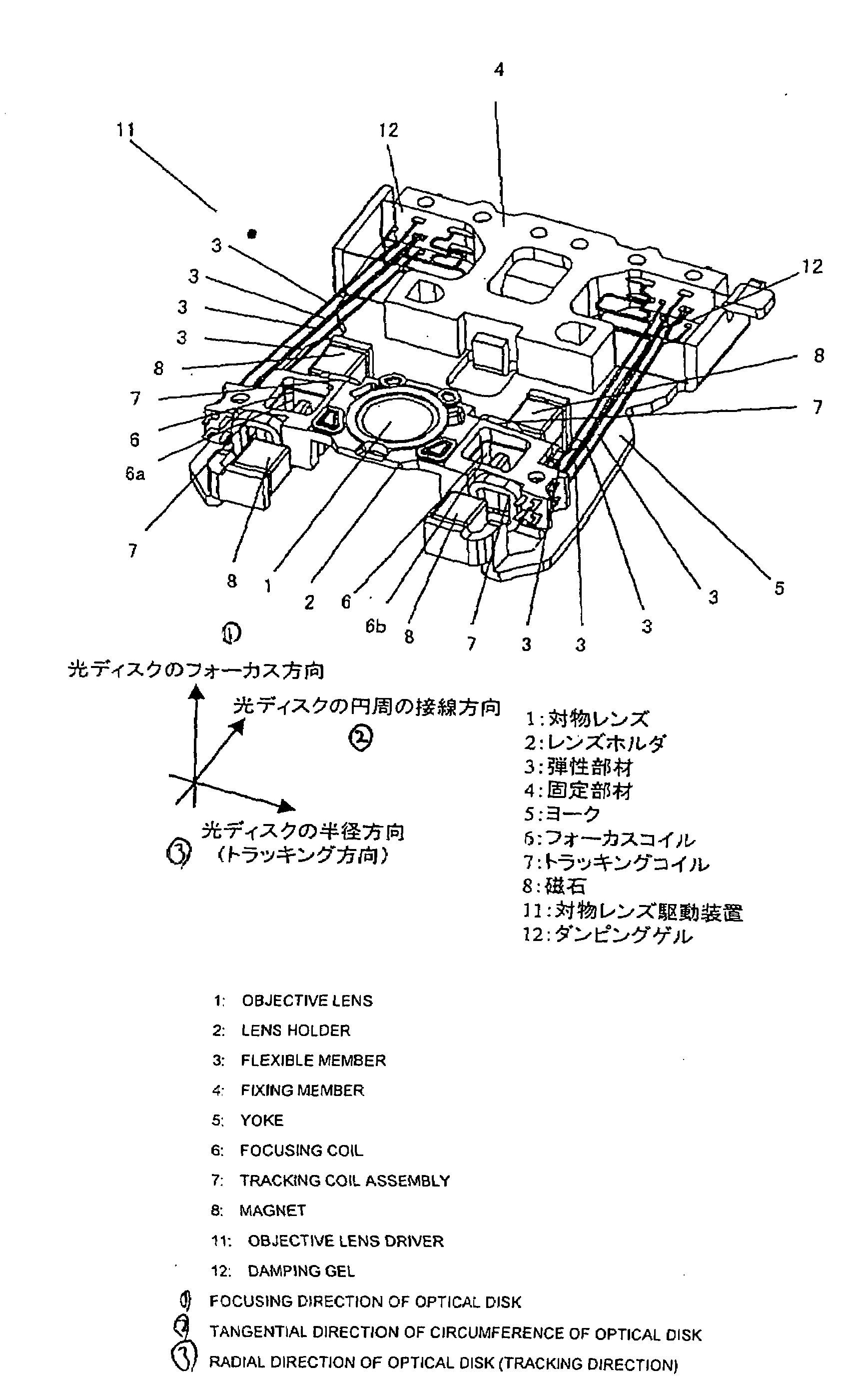
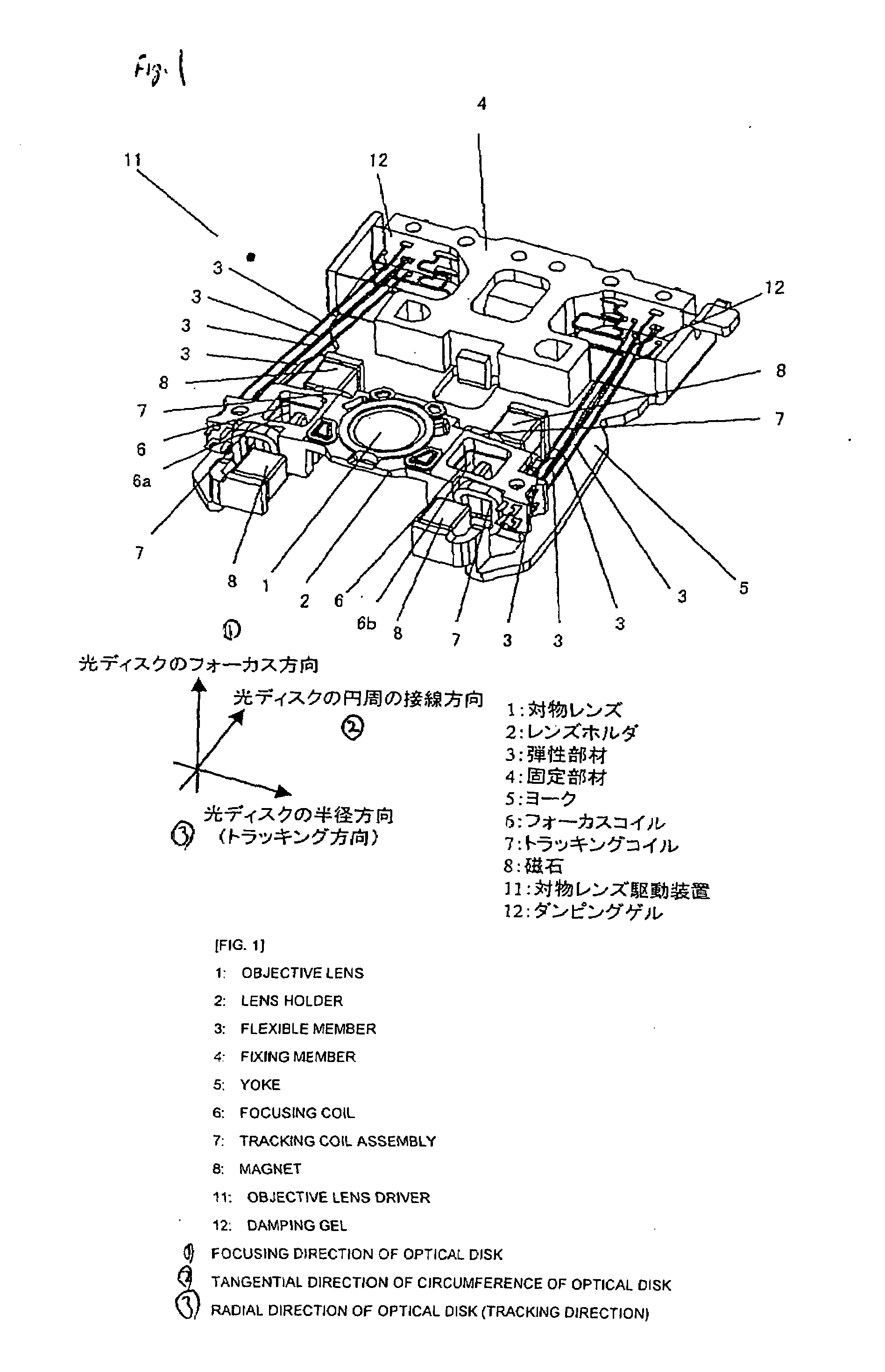
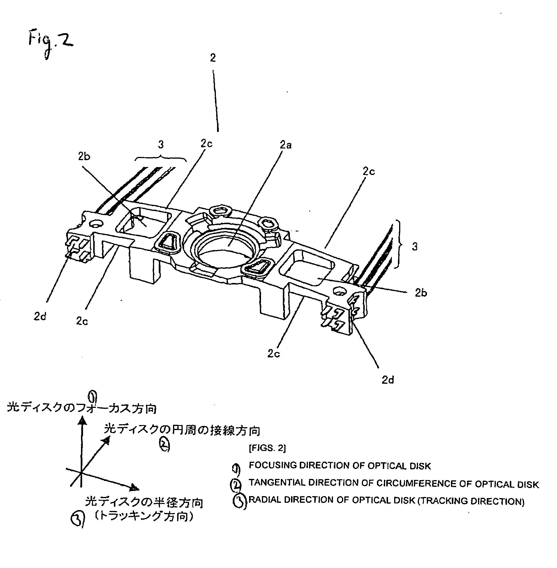
[0189]A first embodiment of the present invention will now be described while referring to drawings. FIG. 1 is a diagram showing the configuration of an objective lens driver according to the first embodiment. In an objective lens driver 11 for the first embodiment, an objective lens 1, focusing coils 6 and a tracking coil assembly 7 are fixed at predetermined locations on a lens holder 2. Further, a fixing member 4 is fixed to a yoke 5, to which magnets 8 are secured, and this assembly is called a driver main body. One end each of individual flexible members 3 is fixed to the lens holder 2 and the other end is fixed to the fixing member 4. The lens holder 2 is supported by the flexible members 3. These flexible members 3 are arranged in multiple columns at both ends of the lens holder 2, and in this embodiment, the flexible members 3 are arranged in two columns and in two rows. When six flexible members 3 are required for connection to the focusing coils 6 and the tracking coil ass...

second embodiment

[0218]A second embodiment of the present invention will now be described while referring to the drawings. For an objective lens driver of the second embodiment, structures differing from those of the first embodiment are provided for a first focusing coil and a second focusing coil. Since the objective lens driver and the manufacturing method for the second embodiment are the same as those for the first embodiment, except for the structures of the first and the second focusing coils and the connections to flexible members, the explanation given for the first embodiment is employed. FIG. 9 is a diagram showing the wire winding directions of the first focusing coil and the second focusing coil in the second embodiment. FIG. 10A is a diagram showing the connections of the focusing coils and a tracking coil assembly to the flexible members when viewed from the side opposite a fixing member. And FIG. 10B is a diagram showing these connections when viewed from the fixing member. As well a...

third embodiment

[0224]A third embodiment of the present invention will now be described while referring to the drawings. The third embodiment relates to an optical pickup device that employs an objective lens driver that was explained in either the first or the second embodiment. FIG. 11 is a diagram showing the configuration of the optical system of the optical pickup device for the third embodiment, and FIG. 12 is a top view of the arrangement of the optical pickup device of the third embodiment. For an optical pickup device 35 in the third embodiment, an objective lens driver 11 mounting an objective lens 1 is fixed to a base 34. Also, a laser source 21, a diffraction element 22, a beam splitter 23, a mirror 24, a collimating lens 25, a wave plate 26, an angle conversion prism 27, a path elevating prism 28, an astigmatism lens 30, a light receiving sensor 31, a filter 32 and a forelight monitor 33 are directly fixed to the base 34 or are fixed thereto through attachment members.

[0225]First, the ...


PUM

PropertyMeasurementUnit
thicknessaaaaaaaaaa
thicknessaaaaaaaaaa
thicknessaaaaaaaaaa

Abstract

An objective lens driver includes: a lens holder, for holding an objective lens; a first focusing coil, for moving one end of the lens holder in the focusing direction; a second focusing coil, for moving the other end of the lens holder in the focusing direction; a tracking coil assembly, for moving the lens holder in the tracking direction; and flexible members, which includes a first flexible member pair, for feeding a current to the first focusing foil, a second flexible member pair, for feeding a current to the second focusing coil, and a third flexible member pair, for feeding a current to the tracking coil assembly, wherein the lens holder is flexibly supported at a driver main body by the flexible members, and wherein the flexible members are arranged in a plurality of columns on both ends of the lens holder.

Description

BACKGROUND[0001]1. Field of the Invention[0002]The present invention relates to an objective lens driver to preferably be mounted on an electronic apparatus, such as a personal computer, a method for manufacturing the objective lens driver, an optical pickup device and an optical disk apparatus.[0003]2. Description of the Related Art[0004]Optical disk apparatuses have been changed from CDs (Compact Discs) to DVDs (Digital Versatile Discs), and further, BDs (Blue-ray Discs) and HD DVDs (High Definition DVDs) have been developed. On the other hand, optical disk apparatuses have been developed by adding not only functions for simply reproducing information recorded on optical disks, but also functions for recording information on optical disks. Furthermore, optical pickup devices that are mounted on optical disk apparatuses to perform the recording and reproduction of information relative to optical disks have also been advanced, in consonance with these developments.[0005]FIG. 15 is a...

Claims


Application Information

Patent Timeline
Patent Type & Authority Applications(United States)
IPC IPC(8): G11B7/00
CPCG11B7/0932G11B7/0935G11B7/0933
Inventor URAGAMI, SUSUMUTANAKA, SHINJIYOSHIMOTO, JUNICHISHUTO, SHINJITOYODA, HIDEKI
Owner PANASONIC CORP
Why Eureka
Try Eureka