Imprint apparatus and method of manufacturing article

Active Publication Date: 2016-07-07
CANON KK
View PDF4 Cites 2 Cited by
  • Summary
  • Abstract
  • Description
  • Claims
  • Application Information

AI Technical Summary

Benefits of technology

[0007]The present invention provides, for example, an imprint apparatus which is advantageous in accurately

Problems solved by technology

With an increase in the complexity of the apparatus arrangement of an imprint apparatus, it is more difficult to arrange a measurement unit for measuring the inclination of the surface of a substrate near a contact position where a mold is brought into contact with an imprint material.
However, for example, there is a case that the distortion of a base plate, on which a stage holding a substrate moves,

Method used


Image

  • Imprint apparatus and method of manufacturing article
  • Imprint apparatus and method of manufacturing article
  • Imprint apparatus and method of manufacturing article

Examples


Example

First Embodiment

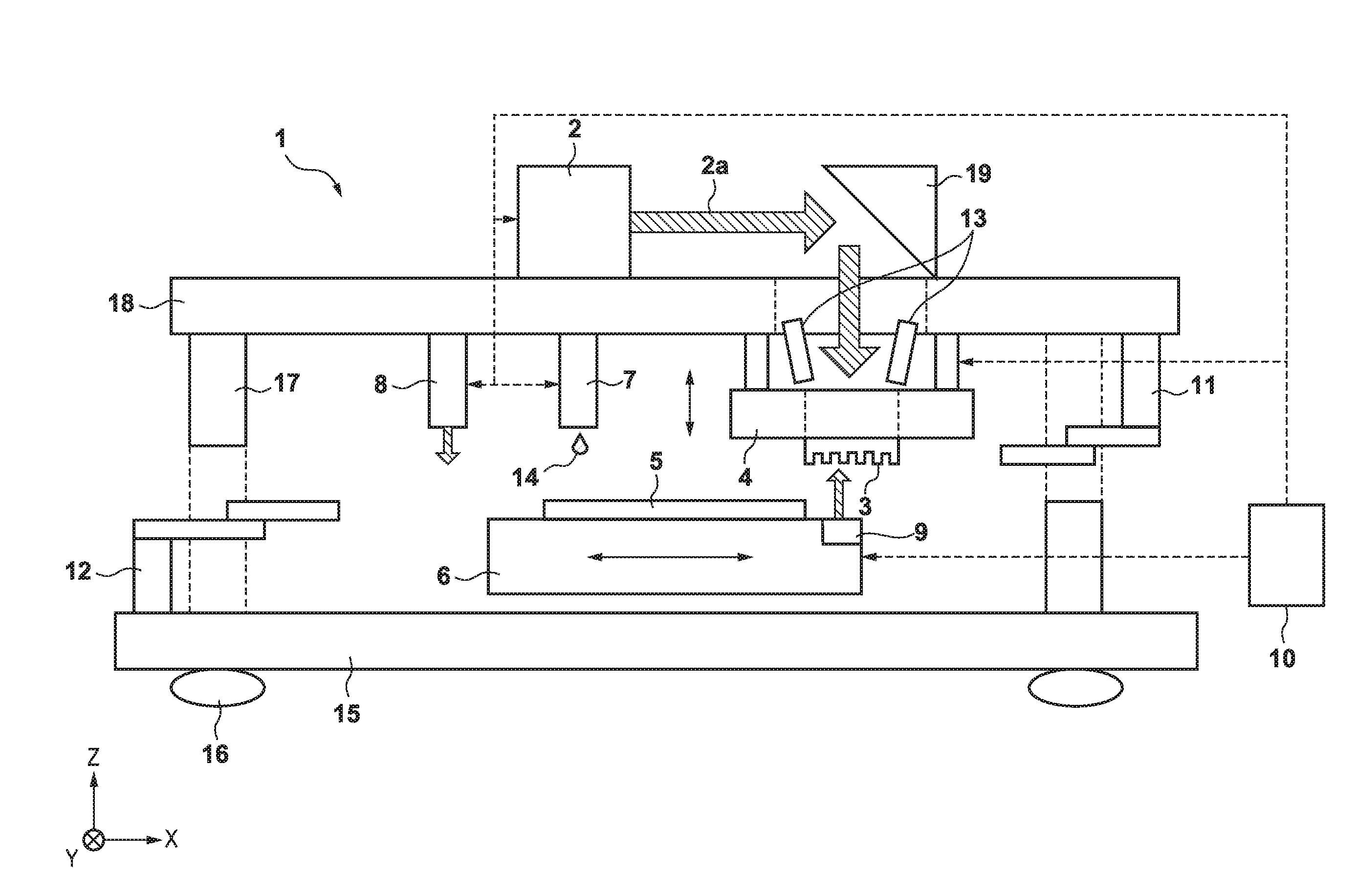
[0025]An imprint apparatus 1 according to the first embodiment of the present invention will be described with reference to FIG. 1. The imprint apparatus 1 is used to manufacture semiconductor devices and the like and configured to perform an imprint process of molding an imprint material 14 on a substrate by using a mold 3, on which a concave-convex pattern is formed, with respect to each of a plurality of shot regions formed on a substrate 5. For example, the imprint apparatus 1 cures the imprint material 14 while the mold 3 on which the pattern is formed is in contact with the imprint material 14 on the substrate. The imprint apparatus 1 then changes the distance between the mold 3 and the substrate 5 to separate (release) the mold 3 from the cured imprint material 14, thereby forming a concave-convex pattern on the imprint material 14 on the substrate. Methods of curing the imprint material 14 include a thermal cycle method using heat and a photo-curing method. T...

Example

Second Embodiment

[0057]An imprint apparatus according to the second embodiment of the present invention will be described. The inclination of the surface of a substrate 5 subjected to an imprint process sometimes varies depending on the position on the surface of the substrate 5. In this case, the relative inclination between the pattern surface of a mold 3 and the surface of the substrate 5 may be controlled by using a correction value determined in accordance with a position (the position of a target shot region) on the surface of the substrate 5 subjected to an imprint process (a position of a target shot region). For this reason, the imprint apparatus according to the second embodiment determines the distribution of correction values corresponding to positions on the surface of the substrate 5 subjected to an imprint process, and obtains a corrected distribution by correcting the distribution of inclinations of the surface of the substrate 5, measured by a first measurement unit...

Example

Third Embodiment

[0065]With an increase in the complexity of the apparatus arrangement of an imprint apparatus, it is becoming difficult to arrange a measurement unit for measuring the inclination of the surface of a substrate near the contact position where a mold is brought into contact with an imprint material. For this reason, it is desirable for an imprint apparatus to measure the inclination of the surface of a substrate at a contact position without using the measurement unit. The imprint apparatus according to the third embodiment measures the inclination of the surface of the substrate 5 by obtaining the height of each of a plurality of portions on the surface of a substrate 5 subjected to an imprint process by bringing the mold 3 into contact with each of the plurality of portions without using a first measurement unit 8. FIG. 14 is a flowchart showing an operation sequence for an imprint process according to the third embodiment. In this case, since the imprint apparatus a...


PUM

PropertyMeasurementUnit
Heightaaaaaaaaaa

Abstract

The present invention provides an imprint apparatus which forms a pattern on an imprint material on a substrate by using a mold, the apparatus comprising a measurement unit configured to measure an inclination of a surface of the substrate at a second position different from a first position where the mold is brought into contact with the imprint material, and a control unit configured to control at least one of inclinations of a surface of the mold and the surface of the substrate when bringing the mold into contact with the imprint material at the first position, wherein the control unit controls at least one of the inclinations based on information representing inclinations of a surface of a reference substrate at the first position and the second position, and a measurement result obtained by the measurement unit.

Description

BACKGROUND OF THE INVENTION[0001]1. Field of the Invention[0002]The present invention relates to an imprint apparatus and a method of manufacturing an article.[0003]2. Description of the Related Art[0004]An imprint apparatus which forms a pattern on an imprint material on a substrate by using a mold having a pattern surface on which a pattern is formed has attracted attention as one of mass production lithography apparatuses for semiconductor devices and the like. The imprint apparatus cures an imprint material on a substrate while a mold is in contact with the imprint material, and separates the mold from the cured imprint material, thereby forming a concave-convex pattern on the imprint material on the substrate.[0005]The imprint apparatus may make the “residual layer thickness of an imprint material” uniform on a substrate. This residual layer thickness indicates the thickness of the imprint material between the substrate and a concave portion of a concave-convex pattern formed o...

Claims


Application Information

Patent Timeline
IPC IPC(8): B29C43/58B29C43/02B29C33/42H01L21/02
CPCB29C43/58H01L21/02318B29C43/02B29L2031/34B29C2043/5825B29C2043/5833B29C33/424G03F7/0002G03F7/0017
Inventor HATTORI, TADASHI
Owner CANON KK
Why Eureka
Try Eureka