Heavy duty pneumatic tire and method of manufacturing the same

a pneumatic tire and heavy duty technology, applied in the direction of tyres, vehicle components, tyre beads, etc., can solve the problems of excessive thickening of the bead portion, repeated stress on the turnup end and fear of growing separation along the turnup portion of the carcass ply

Inactive Publication Date: 2002-04-30
BRIDGESTONE CORP
View PDF12 Cites 7 Cited by
  • Summary
  • Abstract
  • Description
  • Claims
  • Application Information

AI Technical Summary

Problems solved by technology

As a result, the turnup end of the carcass ply is repeatedly subjected to stress, whereby it is apt to cause separation of the turnup end from rubber and hence there is caused a fear of growing the separation along the turnup portion of the carcass ply.
When the length is less than 15 mm, it is difficult to enhance the resistance to the pull-out of the carcass ply cord, while when it exceeds 25 mm, the thickness of the bead portion becomes excessively thick and rapid bending of the turnup portion of the carcass ply wound around the bead core can not be avoided at a place separated outward from the vicinity of the bead core in the widthwise direction of the tire and hence there is a fear of causing the concentration of stress in such a place.

Method used


Image

  • Heavy duty pneumatic tire and method of manufacturing the same
  • Heavy duty pneumatic tire and method of manufacturing the same
  • Heavy duty pneumatic tire and method of manufacturing the same

Examples


first embodiment

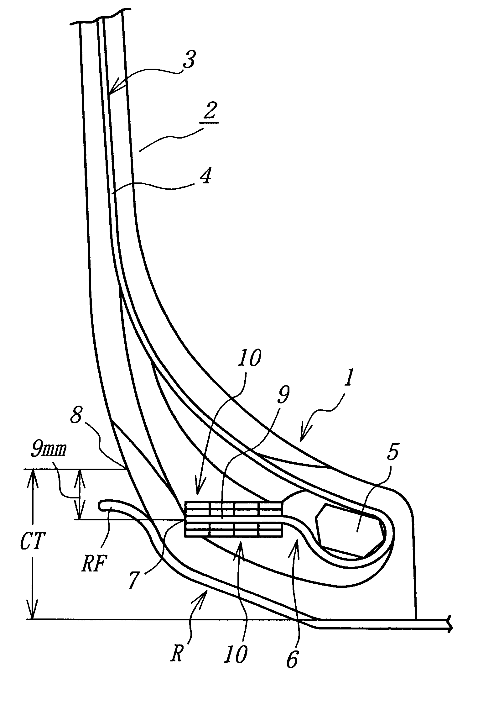
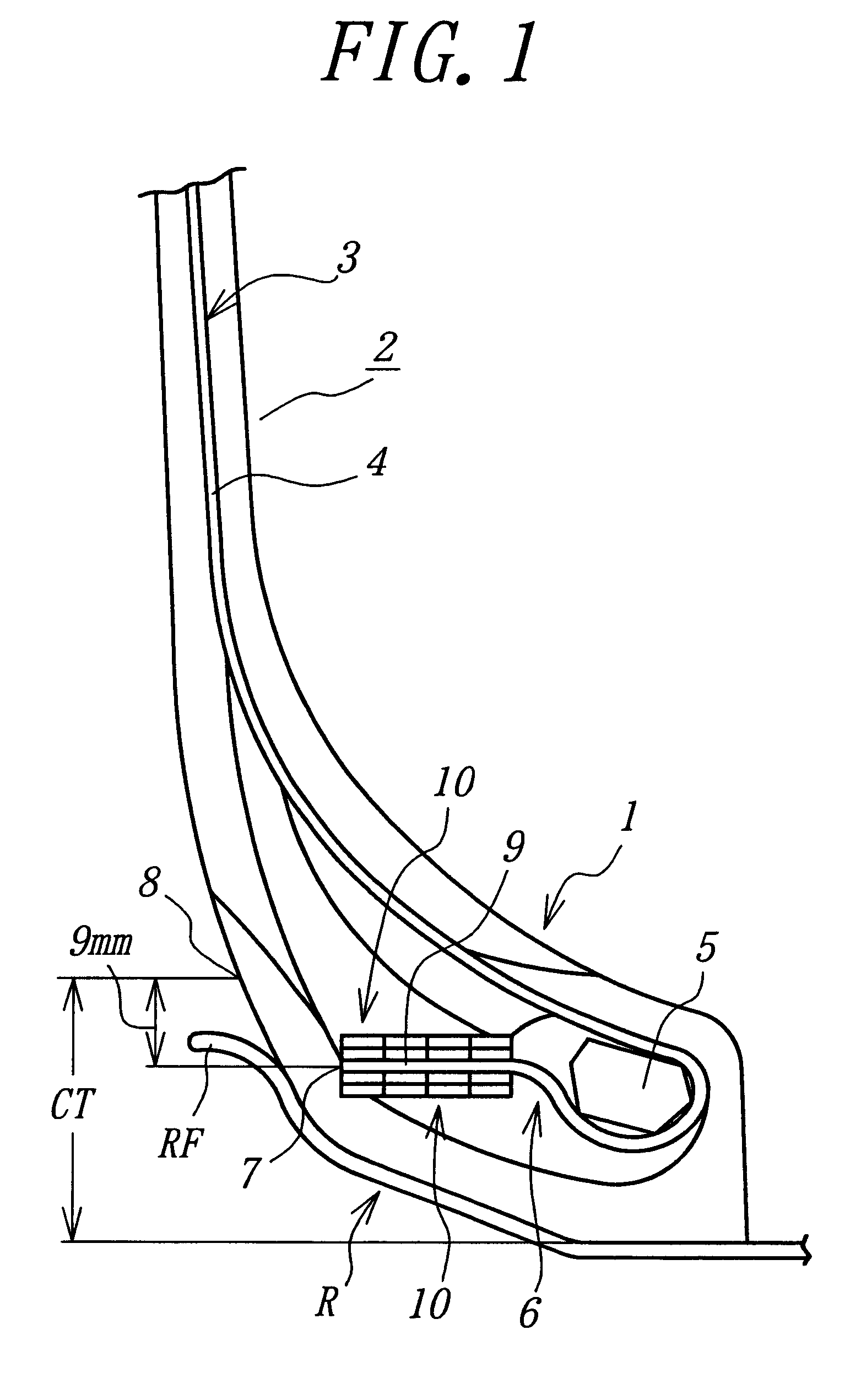
In FIG. 1 is sectionally shown a main part of the heavy duty pneumatic tire according to the invention, wherein numeral 1 is a bead portion located at an innermost peripheral side in a radial direction of the tire, numeral 2 a sidewall portion continuously extending outward from the bead portion 1 in the radial direction, and numeral 3 a carcass constituting a skeleton structure of the tire.

The carcass 3 is comprised of at least one carcass ply 4 (usually plural carcass plies), which is wound around a bead core 5 embedded in an inner end part of the respective bead portion 1 in the radial direction from an inside toward an outside in a widthwise direction of the tire to form a turnup portion 6. A turnup end 7 of the turnup portion 6 is located in a zone CT of the bead portion 1 contacting with a rim R in the radial direction of the tire. In this case, an outer peripheral edge position 8 of the bead portion 1 contacting with the rim R is an outermost peripheral side position of the b...

second embodiment

In FIG. 5 is sectionally shown the heavy duty pneumatic tire according to the invention, wherein the bead core 5 is made of the same material as the winding wire 10.

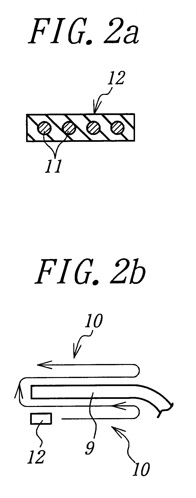
As shown in FIG. 6, the above bead portion structure can be realized by forming the bead core 5 on the end portion of the carcass ply 4 and subsequently forming the winding wires 10 at the inner and outer peripheral sides of the end part 9 of the turnup portion of the carcass ply 4.

In any case, the turnup portion 6 of the carcass ply 4 is sufficiently and strongly sandwiched between the winding wires 10 and the like, whereby the length of the turnup portion 6 can be made shorter than that in the conventional technique and a fear of causing the pull-out of the carcass ply cord can sufficiently removed. And also, the turnup end 7 is located in the zone CT of the bead portion 1 contacting with the rim R in the radial direction of the tire, whereby the deformation of the bead portion 1 in the vicinity of the turnup end durin...


PUM

PropertyMeasurementUnit
lengthaaaaaaaaaa
thicknessaaaaaaaaaa
lengthaaaaaaaaaa

Abstract

A heavy duty pneumatic tire comprises a carcass toroidally extending between a pair of bead cores embedded in bead portions and comprised of at least one rubberized carcass ply, wherein the carcass ply is wound around the bead core from an inside of the tire toward an outside thereof in a radial direction so as to locate a turnup portion in a zone of a bead portion contacting with a rim, and a turnup portion of the carcass ply is sandwiched between winding wires.

Description

1. Field of the InventionThis invention relates to a heavy duty pneumatic tire and a method of manufacturing the same, and more particularly to a heavy duty pneumatic tire capable of sufficiently removing a fear of causing pull-out of carcass ply cord and advantageously preventing the occurrence of separation failure at a turnup portion of the carcass ply by improving a structure of a bead portion.2. Description of Related ArtIn the usual heavy duty pneumatic radial tire, in order to prevent the pull-out of the carcass ply cord during the running of the tire under loading, the turnup portion of the carcass ply wound around a bead core from an inside of the tire toward an outside thereof is largely turned outward in the radial direction of the tire and strongly fastened by embedding in rubber.In such a conventional technique, the turnup end of the carcass ply is located outward from a contact area of the bead portion with a rim in the radial direction of the tire, so that a part of t...

Claims


Application Information

Patent Timeline
Patent Type & Authority Patents(United States)
IPC IPC(8): B29D30/32B29D30/48B60C15/05B29D30/06B29D30/20B60C15/04B60C15/00
CPCB29D30/32B60C15/05B60C15/0081B29D30/48
Inventor SAEKI, TSUTOMU
Owner BRIDGESTONE CORP
Why Eureka
Try Eureka