
Microprocessor comprising a self-calibrated time base circuit

Active Publication Date: 2005-08-02
STMICROELECTRONICS SRL
View PDF4 Cites 2 Cited by
  • Summary
  • Abstract
  • Description
  • Claims
  • Application Information

AI Technical Summary

Benefits of technology

[0012]The present invention is based on the previously rejected premise according to which providing this second oscillator OSC2 to control the time base signal TBS can, on the contrary, be advantageous.
[0014]Furthermore, oscillators having a low cost price and low current consumption are known, such as RC oscillators (resonant circuit RC used as an oscillator), that can be integrated at lesser cost onto a silicon wafer to produce the oscillator OSC2.
[0015]Therefore, the idea of the present invention is that an oscillator OSC2 operating at a low frequency of some tens to some hundreds of Kilohertz, can prove to be sufficient to control the period Tb of the time base signal TBS, and could allow the main clock circuit CKGEN to be stopped during periods of active halt.
[0018]Another object of the present invention is to provide an integrated circuit having a minimum current consumption during periods of active halt.
[0031]According to one embodiment, the first and the second clock circuits each comprise an oscillator, and the oscillator of the second clock circuit features reduced current consumption and low precision relative to the oscillator of the first clock circuit.

Problems solved by technology

Indeed, the clock circuit CKGEN generally has a high frequency in the order of a few Megahertz and a considerable current consumption due, primarily, to the consumption of the oscillator OSC1 and, secondly, to that of the divider circuit PSC (that varies according to the frequency).
Thus, the residual consumption of the microprocessor in the active halt mode, although reduced by the stopping of the peripheral elements, nonetheless remains considerable.

Method used


Image

  • Microprocessor comprising a self-calibrated time base circuit
  • Microprocessor comprising a self-calibrated time base circuit
  • Microprocessor comprising a self-calibrated time base circuit

Examples


Embodiment Construction

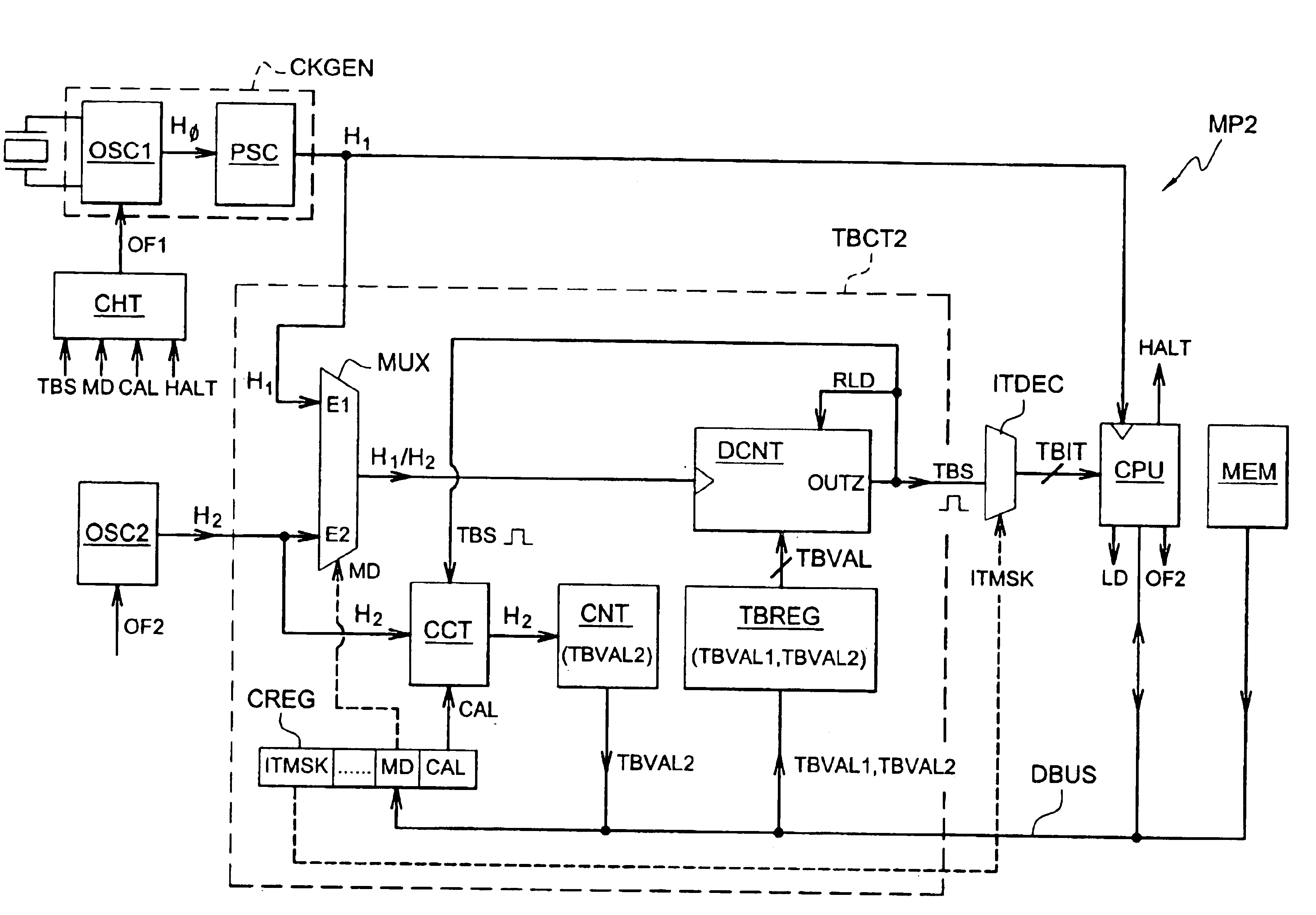
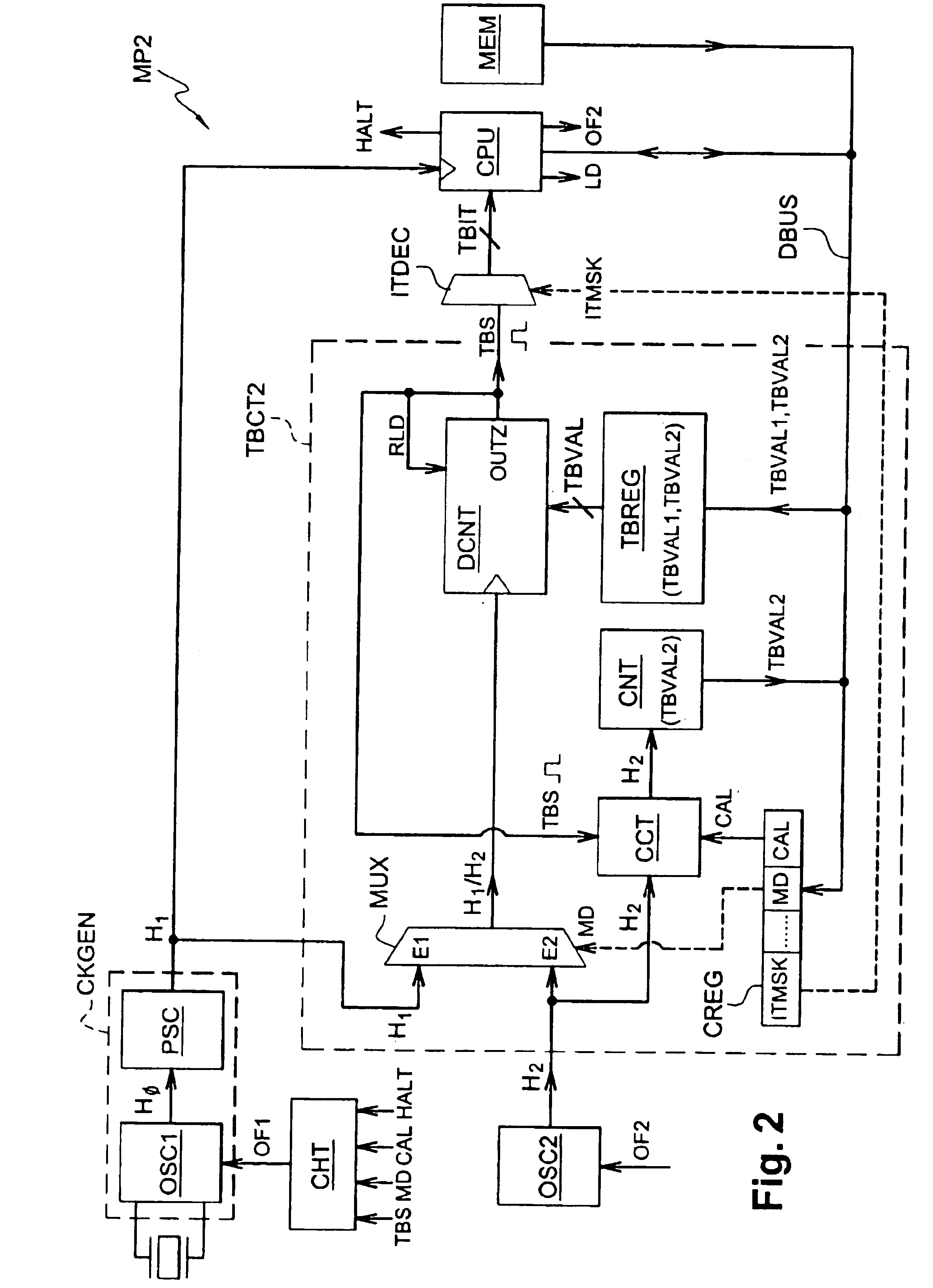
[0042]FIG. 2 schematically represents the architecture of a microprocessor MP2 comprising a time base circuit TBCT2 according to the present invention.

[0043]The microprocessor MP2 comprises, like the classical microprocessor MP1 described above, a central processing unit or CPU, a program memory MEM, a data bus DBUS linking the CPU to the memory MEM, an interrupt decoder ITDEC and a clock circuit CKGEN delivering a primary clock signal H1 applied to the CPU. The clock circuit CKGEN classically comprises a quartz oscillator OSC1 delivering a signal H0 of frequency F0, which is applied to a divider PSC to obtain the clock signal H1, the frequency F1 of which is in the order of a few Megahertz, generally from 1 to 8 MHz. The microprocessor also comprises an oscillator OSC2 delivering a clock signal H2. The oscillator OSC2 is an oscillator with low current consumption, such as an oscillator RC, having an oscillation frequency F2 in the order of a few kilohertz to a few hundred kilohertz...


PUM


Abstract

The present invention relates to an integrated circuit comprising a first clock circuit delivering a first clock signal, a second clock circuit delivering a second clock signal, a first counting circuit for delivering a time base signal using a clock signal and a counting value, and means for applying the first clock signal and a first counting value to the first counting circuit, so as to produce a first time base signal. According to the present invention, the integrated circuit comprises means for producing a second time base signal using the second clock signal and a second counting value, and means for calibrating the second counting value such that it is equal or proportional to the number of periods of the second clock signal occurring during a determined time interval equal to a period or to a whole number of periods of the first time base signal. Application particularly to the management of a timer in a microprocessor.

Description

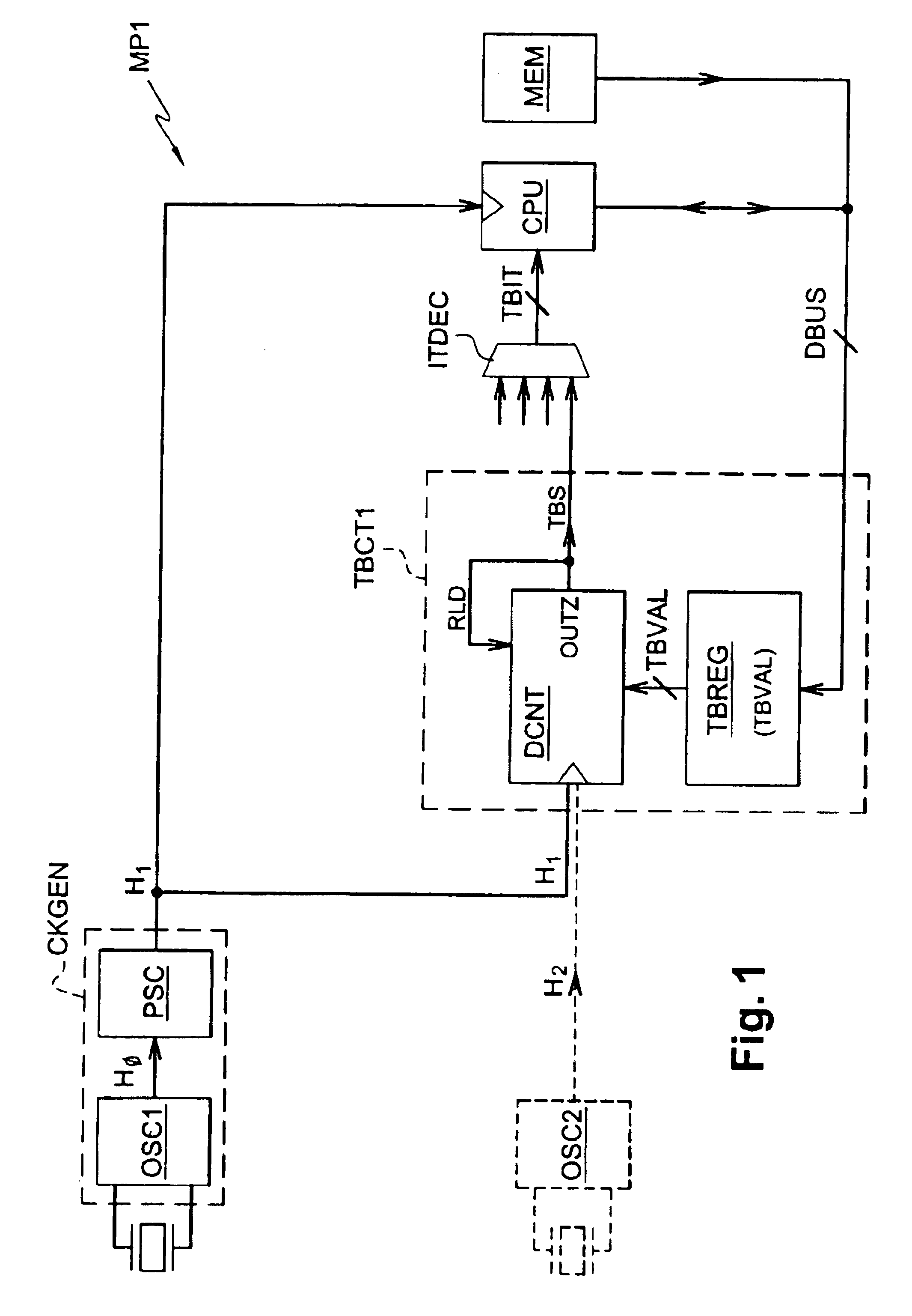
FIELD OF THE INVENTION[0001]The present invention relates to integrated circuits, particularly microprocessors or microcontrollers, comprising a time base signal generating device.BACKGROUND OF THE INVENTION[0002]Time base signals are used extensively in integrated circuits for timing processes, particularly in microprocessors or microcontrollers.[0003]As an example, FIG. 1 very schematically represents the architecture of a microprocessor MP1 comprising a classical time base circuit TBCT1 of the type described in document FR 2 789 501.[0004]The microprocessor comprises a central processing unit or CPU, a program memory MEM, and a data bus DBUS linking the CPU and the memory MEM. The CPU is timed by a primary clock signal H1 supplied by a clock circuit CKGEN comprising a precision oscillator OSC1, such as a quartz oscillator, and a frequency divider PSC (“prescaler”). The oscillator OSC1 delivers a clock signal H0 applied to the divider PSC the output of which delivers the primary c...

Claims


Application Information

Patent Timeline
IPC IPC(8): G06F1/04
CPCG06F1/04
Inventor LENDRE, SANDRINEROCHE, FRANCKPLOURDE, OLIVIER
Owner STMICROELECTRONICS SRL
Learn More