Imaging unit, manufacturing method thereof, and liquid ejecting apparatus

a manufacturing method and liquid ejecting technology, applied in the direction of instruments, optical elements, record information storage, etc., can solve the problems of the adhesive not easily entering the gaps between the abutting portions and the optical members

Active Publication Date: 2015-10-01
SEIKO EPSON CORP
View PDF1 Cites 6 Cited by
  • Summary
  • Abstract
  • Description
  • Claims
  • Application Information

AI Technical Summary

Benefits of technology

[0007]An advantage of some aspects of the invention is to provide an imaging unit capable of suppressing the inclination of the optical member toward the lens barrel, the manufacturing method thereof, and a liquid ejecting apparatus which is provided with the imaging unit.

Problems solved by technology

Accordingly, even if the adhesive of the plurality of adhesive portions enters the gap between the outside surface of the optical member and the inside surface of the lens barrel facing the outside surface, the adhesive does not easily enter the gaps between the abutting portions and the optical member.

Method used


Image

  • Imaging unit, manufacturing method thereof, and liquid ejecting apparatus
  • Imaging unit, manufacturing method thereof, and liquid ejecting apparatus
  • Imaging unit, manufacturing method thereof, and liquid ejecting apparatus

Examples


Embodiment Construction

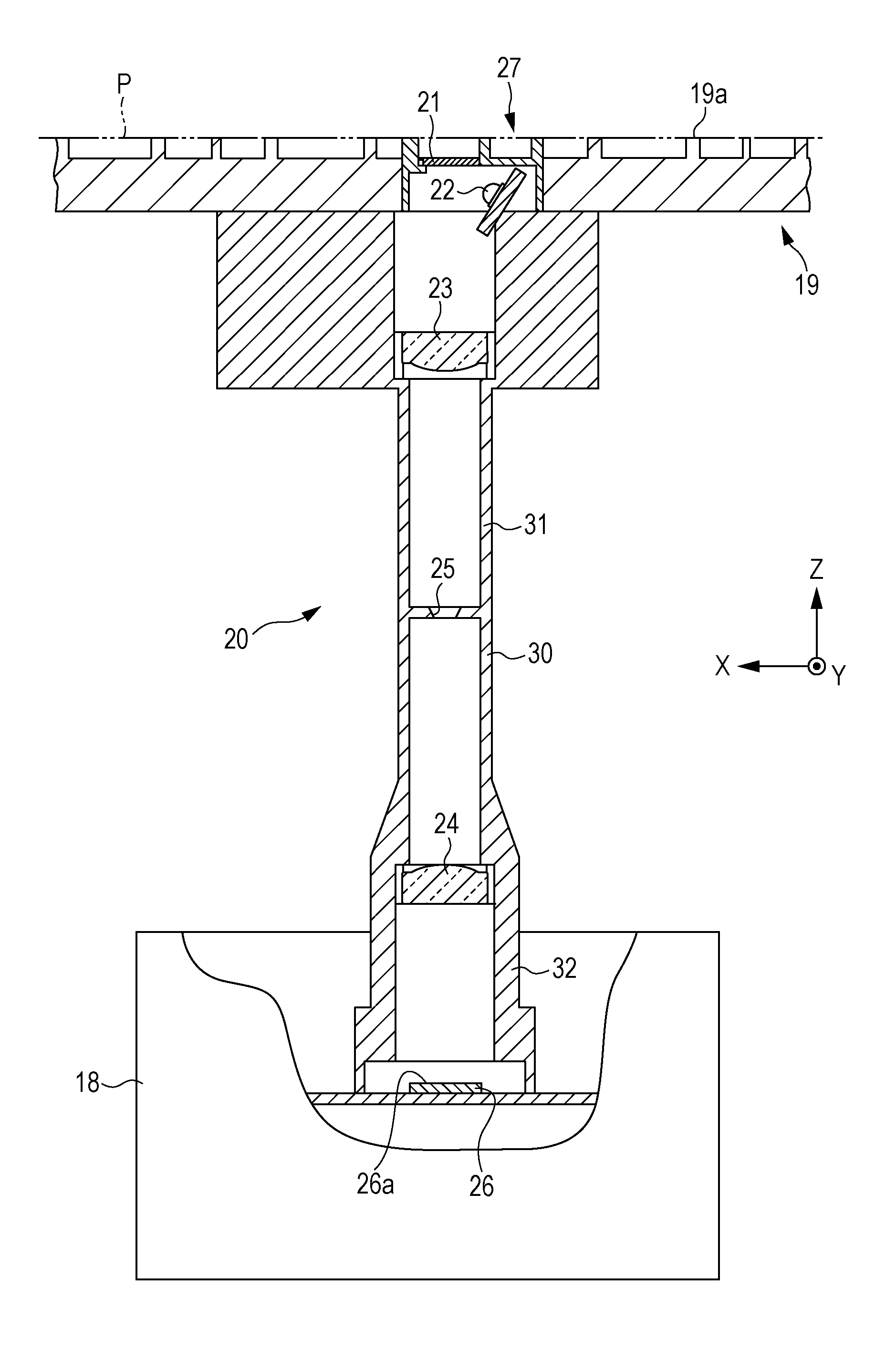
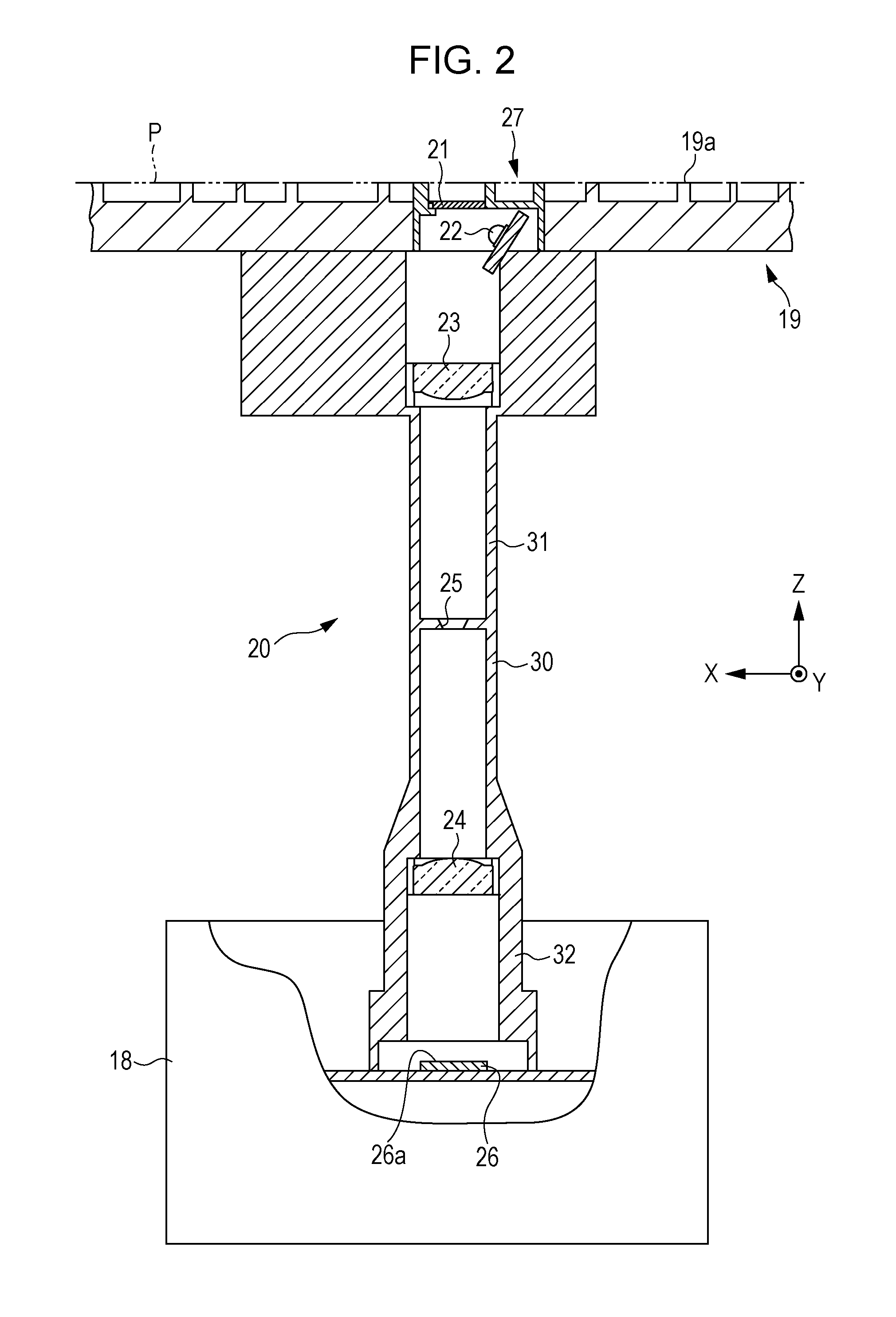
[0052]Hereinafter, description will be given of an ink jet printer as a specific embodiment of the liquid ejecting apparatus, according to the drawings.

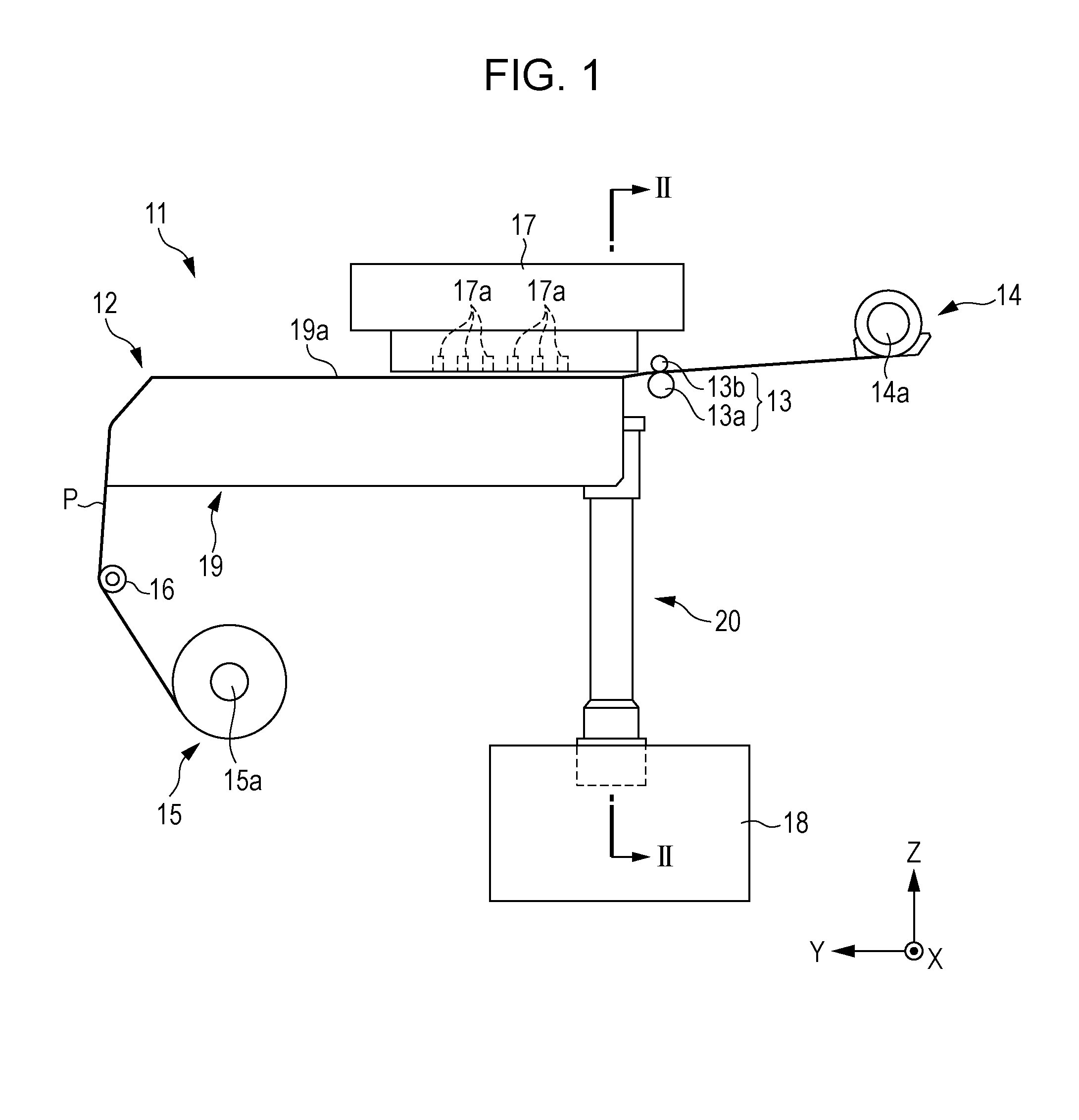
[0053]As illustrated in FIG. 1, the ink jet printer (hereinafter, “printer 11”), which is an example of the liquid ejecting apparatus, is provided with a transport apparatus 12, and an ejecting unit 17. The transport apparatus 12 transports a long sheet-shaped continuous paper P, which is an example of the medium, and the ejecting unit 17 performs printing by ejecting an ink onto the continuous paper P that is transported by the transport apparatus 12. The printer 11 is provided with a control unit 18 which controls the transport apparatus 12 and the ejecting unit 17.

[0054]The transport apparatus 12 is provided with a feed unit 14 and a winding unit 15. The feed unit 14 feeds the continuous paper P, and the winding unit 15 winds up the continuous paper P that is fed out from the feed unit 14 and printed on by the ejecting unit 17. In...


PUM

PropertyMeasurementUnit
anglesaaaaaaaaaa
angleaaaaaaaaaa
angleaaaaaaaaaa

Abstract

An imaging unit is provided with a cylindrical lens barrel, and an object-side lens which is disposed in the lens barrel and is fixed to the lens barrel using an adhesive. The lens barrel includes three abutting portions and three adhesive portions. The object-side lens abuts the three abutting portions in an optical axis direction of the object-side lens, and the adhesive portions are formed between an outer circumferential surface of the object-side lens and an inner circumferential surface of the lens barrel, and the adhesive is injected therein. The three adhesive portions are formed at an interval in a circumferential direction. The three adhesive portions and the three abutting portions do not overlap each other in plan view as seen from a vertical direction.

Description

BACKGROUND[0001]1. Technical Field[0002]The present invention relates to an imaging unit, a manufacturing method thereof, and a liquid ejecting apparatus provided with the imaging unit.[0003]2. Related Art[0004]A liquid ejecting apparatus in which an imaging unit is provided on a supporting portion which supports a medium, a texture of the lower surface of the medium which passes over the medium supporting portion is imaged by the imaging unit, and the transport amount of the medium is detected based on the image that is obtained through the imaging is known as a liquid ejecting apparatus which ejects a liquid such as an ink from an ejecting unit onto a medium such as paper. In such a liquid ejecting apparatus, an opening portion for allowing light from the imaging unit to radiate toward the bottom surface of the medium is formed in the supporting surface of the medium supporting portion (for example, refer to JP-A-2013-119439).[0005]As illustrated in FIG. 15A, an imaging unit 200 o...

Claims


Application Information

Patent Timeline
Patent Type & Authority Applications(United States)
IPC IPC(8): B41J13/00G02B7/02
CPCB41J13/0009G02B7/025G02B7/022B41J2/451B41J11/0095G11B7/00G11B7/0037
Inventor KATAOKA, HIDEYUKIIDE, MITSUTAKAKOBAYASHI, HIROYUKI
Owner SEIKO EPSON CORP
Why Eureka
Try Eureka