
Sheet feeding device and image forming apparatus

a feeding device and image forming technology, applied in the direction of transportation and packaging, thin material processing, article separation, etc., can solve the problems of sheet not being forwarded further, sheet may not always be fed in the feeding path of sheet properly, and may not be fed properly

Active Publication Date: 2011-04-26
BROTHER KOGYO KK
View PDF29 Cites 5 Cited by
  • Summary
  • Abstract
  • Description
  • Claims
  • Application Information

AI Technical Summary

Benefits of technology

The solution effectively prevents irregular feeding by maintaining a consistent angle of the topmost sheet, ensuring reliable sheet feeding and allowing for a more compact image forming apparatus design.

Problems solved by technology

In this regard, because the angle of the topmost sheet with respect to the feed roller is not constant, the sheets may not always be fed in the sheet feeding path properly.
Thus, idle feeding, in which the sheet is not forwarded further, may occur.
Therefore, an angle of the topmost sheet in the sheet stack arranged on the holder plate with respect to the feed roller is not specifically adjustable.

Method used


Image

  • Sheet feeding device and image forming apparatus
  • Sheet feeding device and image forming apparatus
  • Sheet feeding device and image forming apparatus

Examples


Embodiment Construction

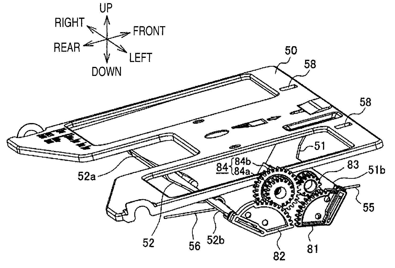
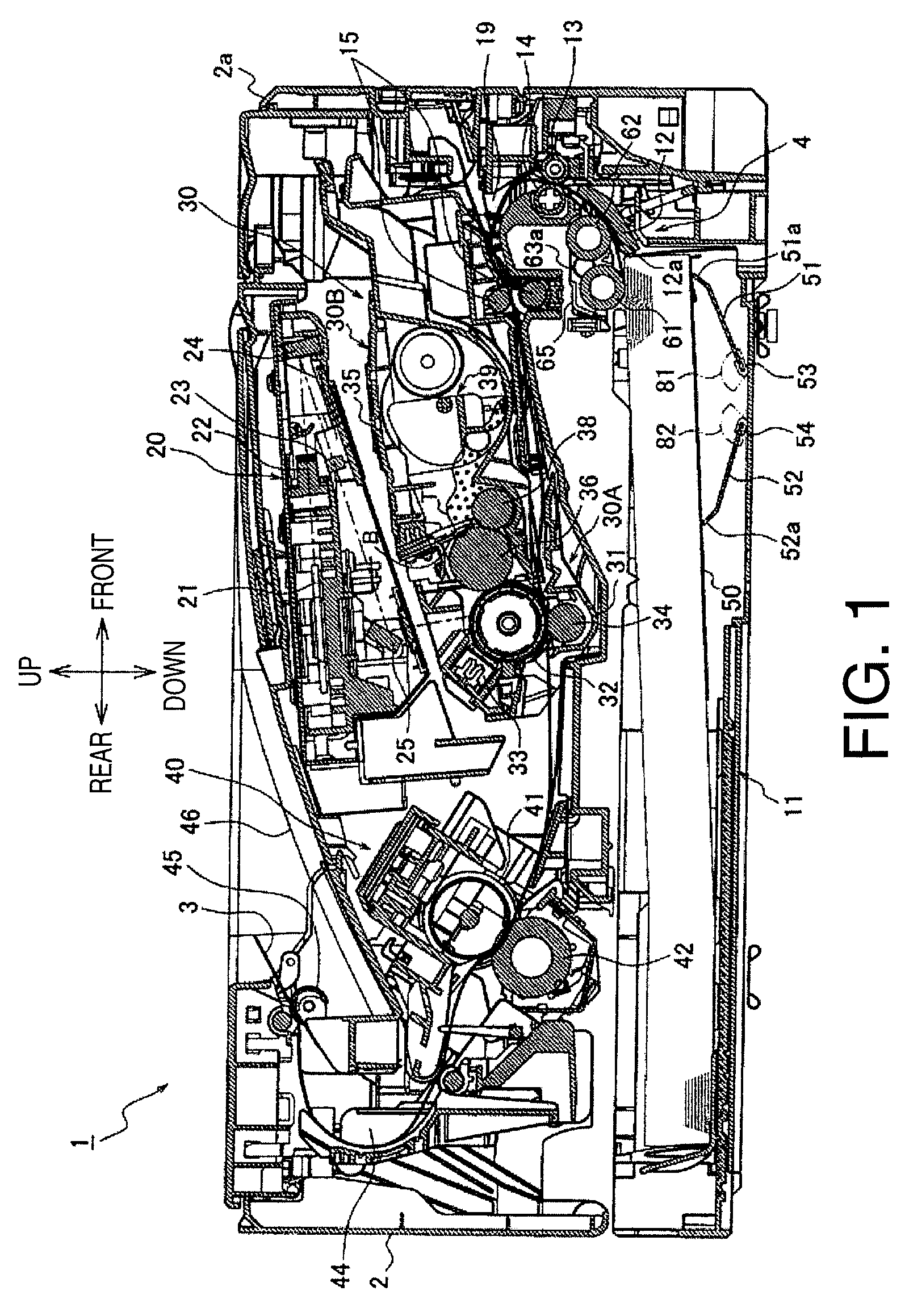
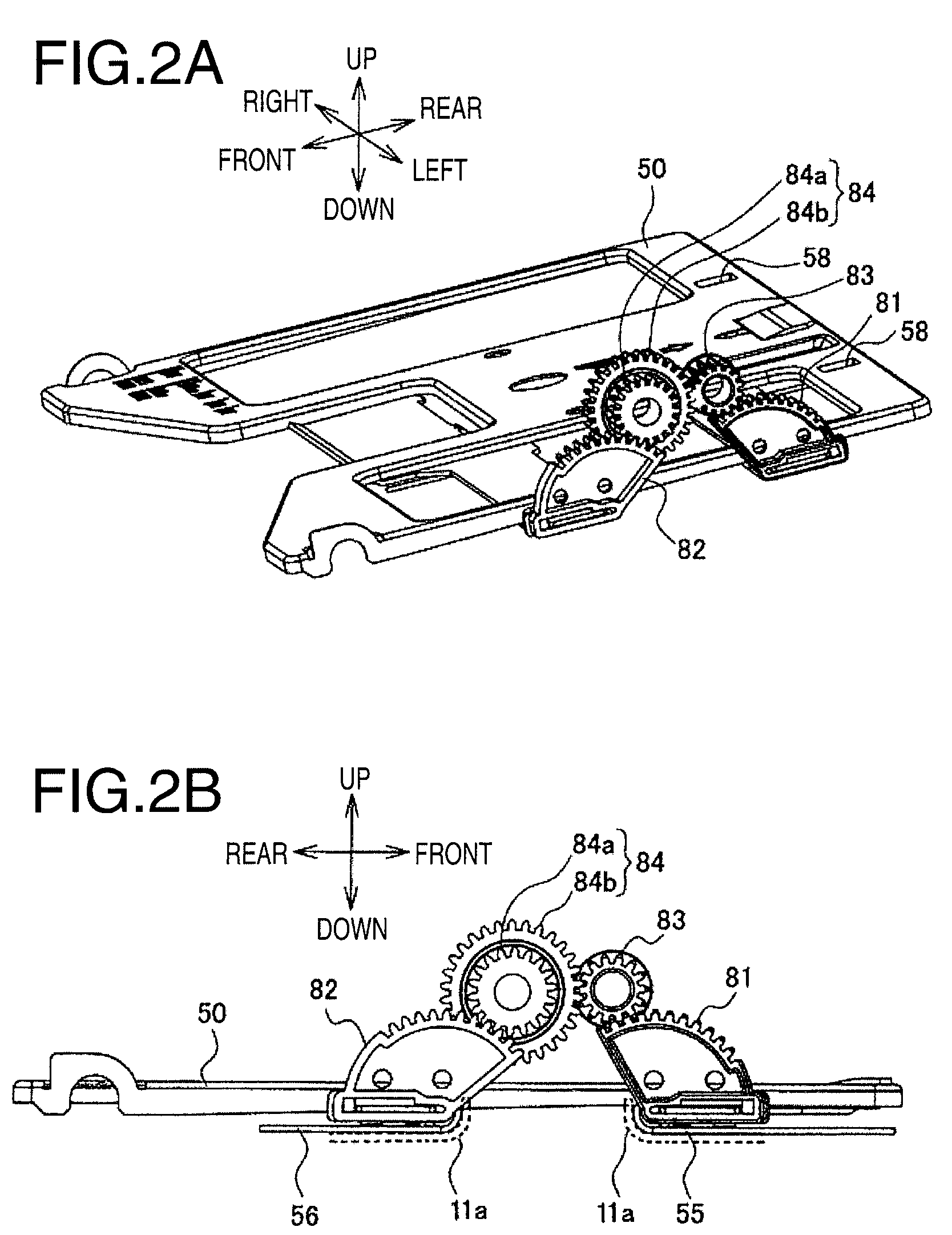
[0025]Hereinafter, embodiments according to aspects of the present invention will be described with reference to the accompanying drawings. FIG. 1 is a cross-sectional side view of a laser printer 1 according to a first embodiment of the present invention. In FIG. 1, a right-hand side is referred to as front of the laser printer 1, and a left-hand side is referred to as rear of the laser printer 1. Further, a near side and a far side are respectively referred to as left and right of the laser printer 1.

[0026]Overall configuration of the laser printer 1 according to the first embodiment will be described. The laser printer 1 includes a feeder device 4 to feed a recording sheet 3, an image forming unit 5 to form an image on the recording sheet 3, and a casing 2 in which the feeder device 4, the image forming unit 5, and other components are stored. The image forming unit 5 is arranged substantially above the feeder device 4. On a front side of the casing 2, an openable / closable front ...


PUM


Abstract

A sheet feeding device is provided. The sheet feeding device includes a sheet holder to hold a sheet in a position to be fed, a feed roller to pick up the sheet, a first lifter to move a closer portion of the sheet holder by one of a front end and a rear end thereof, a second lifter to move a further portion of the sheet holder by one of a front end and a rear end thereof, and a coordinating system to move the first lifter and the second lifter in cooperation with each other to move the overall sheet holder in a direction to be closer to the feed roller, wherein an amount of the sheet holder to be moved by the first lifter is greater according to a constant rate with respect to an amount of the sheet holder to be moved by the second lifter.

Description

CROSS REFERENCE TO RELATED APPLICATION[0001]This application claims priority from Japanese Patent Applications Nos. 2008-086916 filed on Mar. 28, 2008, and 2009-053089 filed on Mar. 6, 2009, the entire subject matters of which are incorporated herein by reference.BACKGROUND[0002]1. Technical Field[0003]An aspect of the present invention relates to a sheet feeding device having a shifting unit to move a holder plate, holding a stack of sheets, toward a sheet feeding roller and an image forming apparatus having the sheet feeding device.[0004]2. Related Art[0005]Conventionally, an image forming apparatus having a detachable sheet cassette, in which a stack of recording sheets are contained, in a bottom portion thereof has been known. The stack of recording sheets are held on a swingable holder plate, which is installed on a bottom of the sheet cassette, so that the recording sheets can be picked up by a feed roller and fed in a sheet feeding path to a printing unit. The picked-up recor...

Claims


Application Information

Patent Timeline
Patent Type & Authority Patents(United States)
IPC IPC(8): B65H1/08B65H1/10B65H1/26
CPCB65H1/14B65H1/266B65H2405/1117B65H2403/42B65H2403/41
Inventor OKAMOTO, TSUGIO
Owner BROTHER KOGYO KK
Learn More