

Table installing device
a technology for installing devices and tables, applied in the direction of lighting support devices, washstands, instruments, etc., can solve the problems of degrading the convenience of setting the table installing device b>8/b>
- Summary
- Abstract
- Description
- Claims
- Application Information
AI Technical Summary
Benefits of technology
Problems solved by technology
Method used
Image

Examples
first embodiment
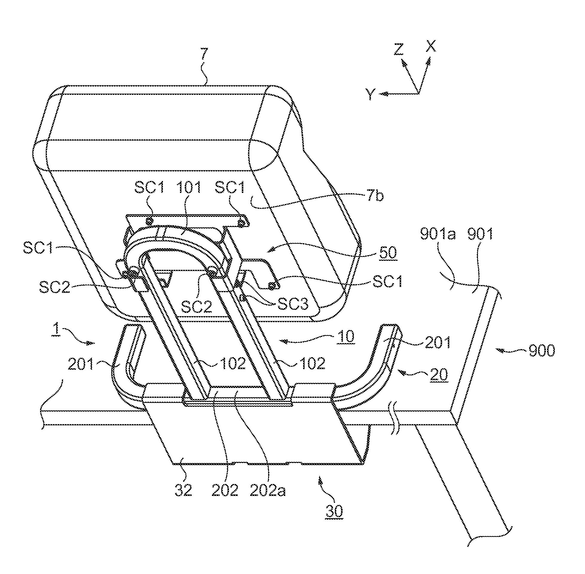
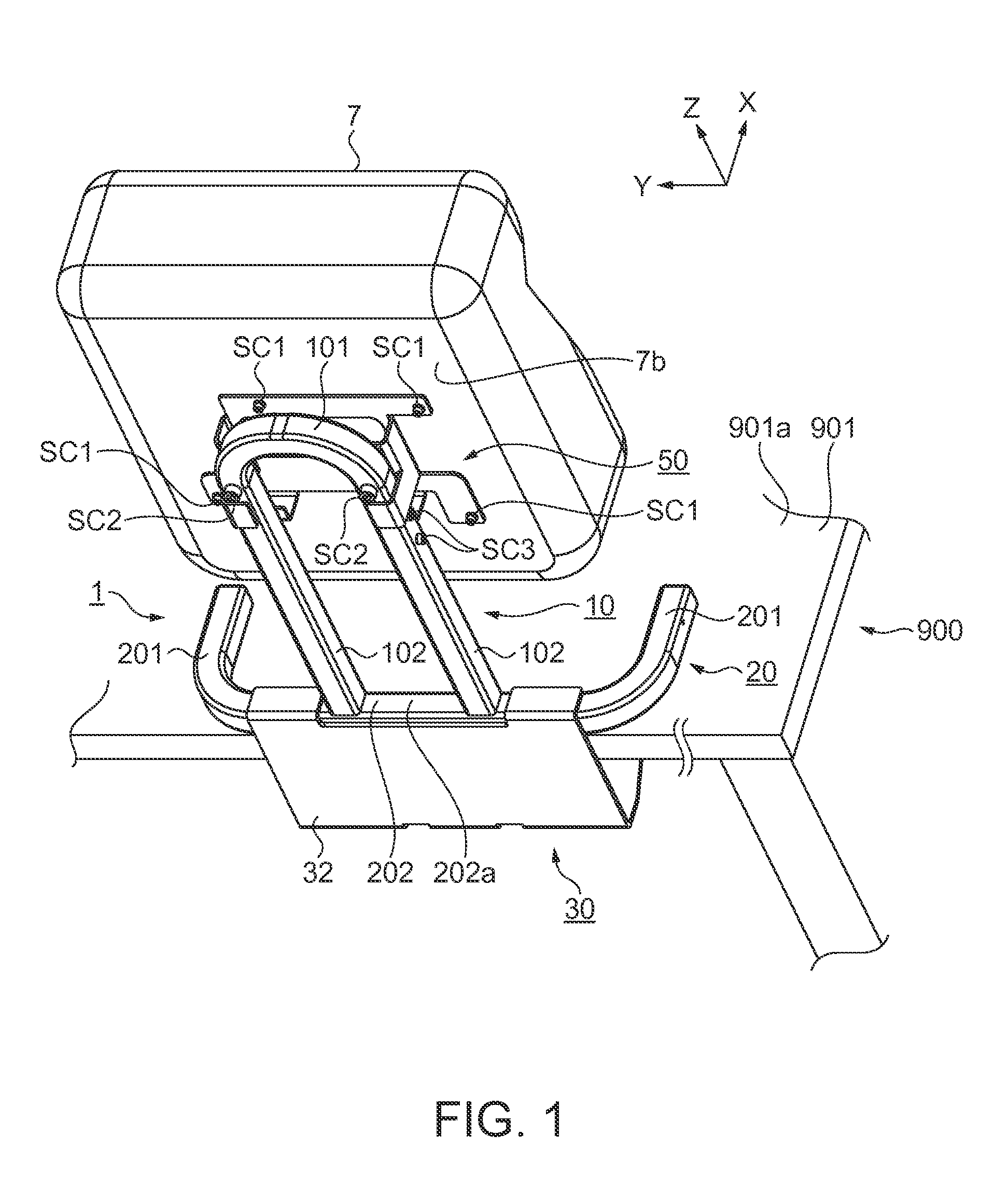
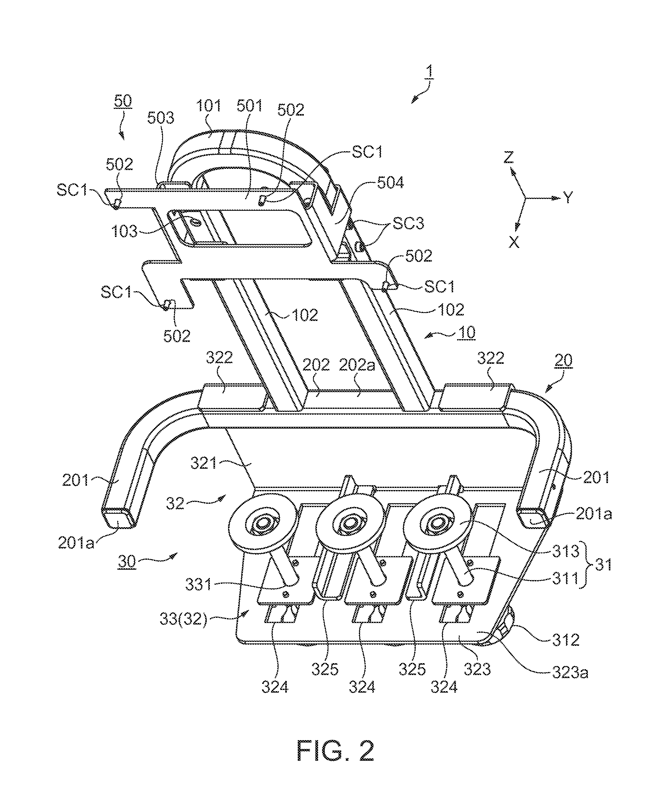
[0031]FIG. 1 is a perspective view showing a state where a projector 7 is installed on a top plate 901 by the use of a table installing device 1 according to a first embodiment. In addition, FIG. 1 is a perspective view in which the table installing device 1 is viewed from a rearward direction. FIG. 2 is a perspective view of the table installing device 1. In addition, FIG. 2 is a perspective view in which the table installing device 1 is viewed from a forward direction. FIG. 3 is an exploded view of the table installing device 1. In addition, FIG. 3 shows an exploded view in which the table installing device 1 is viewed from the rearward direction. FIG. 4 is a side view of a state where the table installing device 1 is installed on the top plate 901. A configuration and an installing method of the table installing device 1 will be described referring to FIGS. 1 to 4.
[0032]As shown in FIG. 1, the table installing device 1 of the present embodiment is a device that installs the proje...
second embodiment
[0083]FIG. 5 is a perspective view showing a state where a projector 71 is installed on the top plate 901 by the use of a table installing device 2 according to s second embodiment. In addition, FIG. 5 is a perspective view in which the table installing device 2 is viewed from the rearward direction. FIG. 6 is a plan view of a case where the table installing device 2 is installed on the top table 901. Incidentally, FIG. 6 shows a plan view in which the table installing device 2 and the table 900 are viewed from the upward direction, and shows a projection external form A of the projection image projected from the projector 71 and an image pickup external form B of the image pickup device 6. A configuration and an operation of the table installing device 2 will be described with reference to FIGS. 5 and 6.
[0084]As shown in FIG. 5, a configuration of a fixing member 60 of the table installing device 2 of the present embodiment is different from the configuration of the fixing member 5...
PUM
 Abstract
Description
Claims
Application Information