A cooling system for axial magnetic bearing

Active Publication Date: 2017-06-01
THERMODYN
View PDF2 Cites 0 Cited by
  • Summary
  • Abstract
  • Description
  • Claims
  • Application Information

AI Technical Summary

Benefits of technology

The invention provides a magnetic bearing system for a rotating flywheel that includes a cooling fluid path. The cooling fluid flows through the flywheel in a radial plane relative to its axis of rotation. The system includes a flow guiding piece that surrounds the flywheel and is crossed by several bores. The bores are angled close to the flywheel and open close to its peripheral surface. The cooling fluid flows through the bores and impacts the flywheel at a speed that is greater than its linear speed of rotation. The cooling fluid flow is sent along a direction of incidence that is perpendicular or oblique to the local radial direction in the area of impact. The system also includes a fluid flow guiding piece that sends the cooling fluid flow to the flywheel in a direction that is perpendicular to the radial direction of the flywheel. The cooling fluid flow interacts with the flywheel to provide rotating mechanical energy to it. The technical effects of the invention include improved cooling of the flywheel, reduced friction caused by the cooling fluid, and improved performance of the magnetic bearing system.

Problems solved by technology

In all cases, the cooling flow rate directly generates an economic loss, either because of a yield loss of the turbomachine (internal system), or because of the cost linked to the investment and use of the external cooling system.
This suggests that the loss of ventilation can be limited or canceled by reducing the existing speed difference at any point between the stop wheel and the cooling fluid.

Method used


Image

  • A cooling system for axial magnetic bearing
  • A cooling system for axial magnetic bearing
  • A cooling system for axial magnetic bearing

Examples


Embodiment Construction

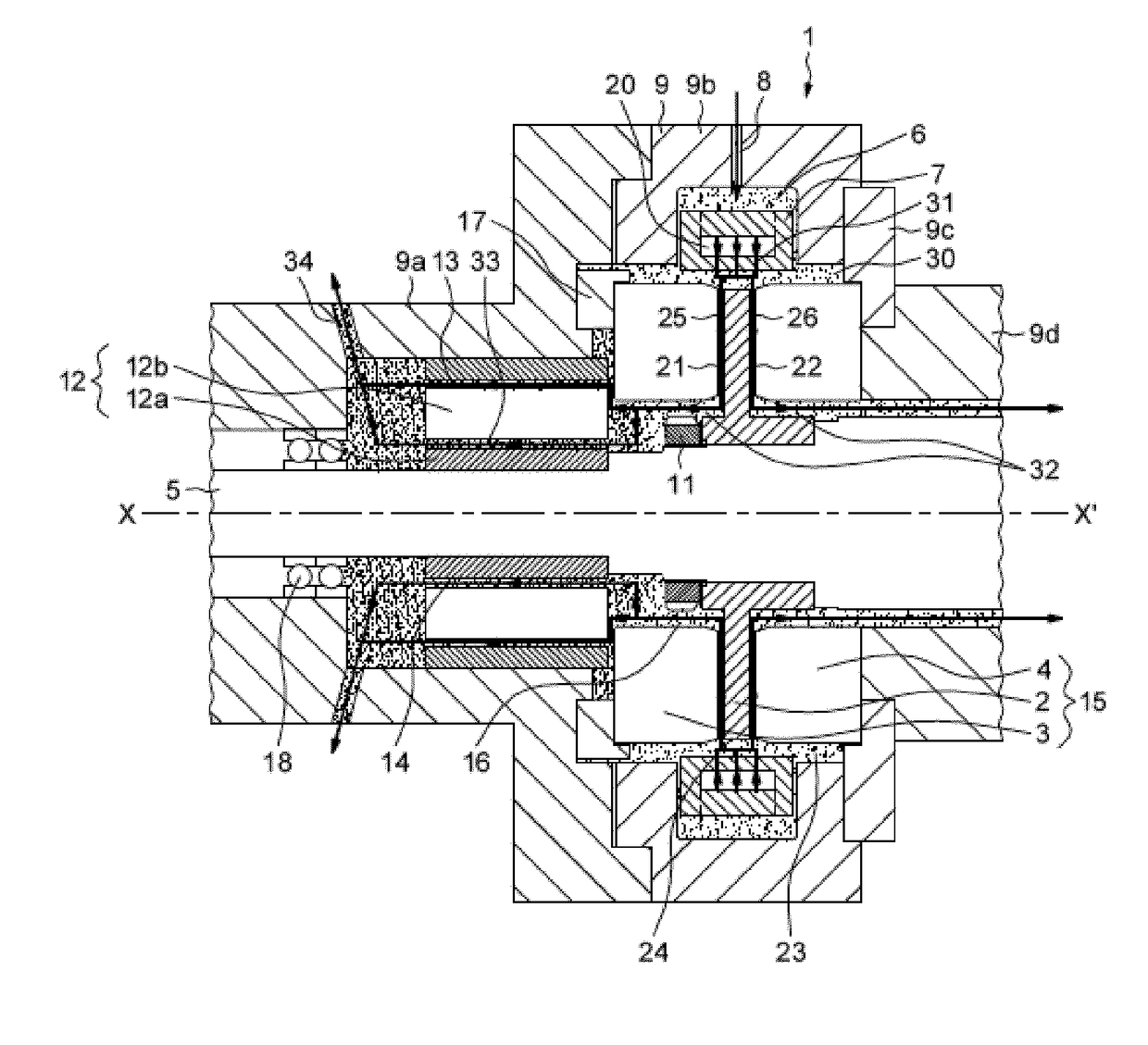
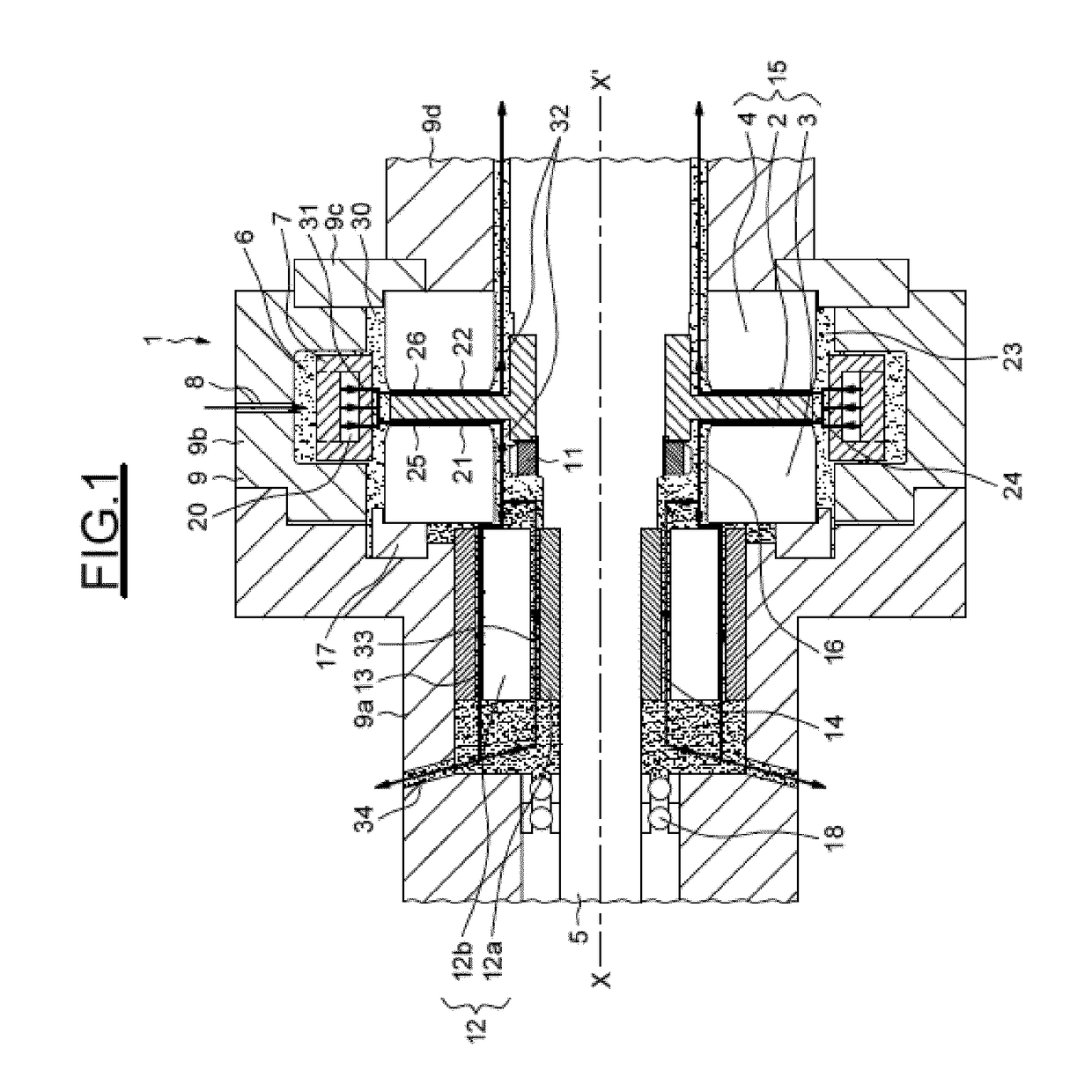
[0042]As illustrated in FIG. 1, a system 1 of magnetic bearing for a rotating machine according to an embodiment of the invention is assembled on a shaft 5 having a geometric axis XX′, comprises a rotating flywheel 2 assembled on the shaft 5, integral in rotation of the shaft 5 and held on the shaft 5 for example by means of a nut 11, comprises a first axial stop 3 and a second axial stop 4 integral with a housing 9 of the bearing system, the housing 9 being fixed. The system includes at least one zone 32 of central radial clearance defining a radial clearance between the shaft 5 or between a central portion of the flywheel 2 surrounding the shaft 5, and stator elements of the magnetic bearing system 1, for example a stop 3 or 4. These zones 32 allow a non-contact rotational movement between the shaft+flywheel assembly and the stator portions surrounding the shaft adjacent the flywheel. These zones 32 also allow, by means of gas lines leading into these zones, to evacuate the gases ...


PUM


Abstract

Embodiments of the present invention provide a magnetic bearing system comprising an axial bearing rotating flywheel arranged so as to magnetically interact with at least one fixed axial stop. The system includes a cooling fluid path configured so as to send the flow to the flywheel in a direction of flow being in a substantially radial plane relative to the axis of rotation of the flywheel.

Description

BACKGROUND[0001]Embodiments of the present invention relate to fluid cooled bearing systems, and particularly systems comprising an axial magnetic bearing cooled by a fluid flow.[0002]Typically, in such a bearing, a fluid flow, for example a gas stream, is injected into one or more air gaps between a rotating flywheel of the axial bearing, and one or more fixed abutments of the axial bearing. The gas stream must be sufficient to evacuate both the calories generated by the magnetic induction phenomena, and the calories generated by the fluid viscous frictions at the air gap. Ventilation loss designates the latter type of loss.[0003]When the bearing system is part of a rotating machine such as a turbine or a compressor, the high flow rates of gas necessary for cooling sometimes lead to establish a cooling fluid circuit configured to cool not only the bearing system, but also to cool other components of the machine.[0004]This cooling circuit can be arranged internally to the machine, u...

Claims


Application Information

Patent Timeline
IPC IPC(8): F16C37/00H02K7/09H02K9/00F04D29/58F04D29/058F01D25/16F01D25/12F16C32/04H02K7/02
CPCF16C37/005F16C32/0476H02K7/09H02K9/005H02K7/02F05D2240/51F01D25/16F01D25/125F04D29/582F16C2360/23F04D29/058F16C32/04F16C37/00F16C39/06H02K9/00
Inventor GUENARD, DENIS GUILLAUME
Owner THERMODYN
Why Eureka
Try Eureka