Cap for an injector

a technology for injectors and caps, which is applied in the direction of intravenous devices, infusion needles, other medical devices, etc., can solve the problems of difficult removal of the needle cap, unsheathing of the needle tip, and the difficulty of the process of removing the cap from the injector

Active Publication Date: 2020-10-01
UCB PHARMA SRL
View PDF0 Cites 0 Cited by
  • Summary
  • Abstract
  • Description
  • Claims
  • Application Information

AI Technical Summary

Benefits of technology

[0041]An over-coating is provided to the recess base of each recessed portion. The over-coating comprises a material that is more flexible (e.g. softer) than the generally rigid material of the cap body. In normal use, the over-coating acts to provide a grip surface for the user's index finger or thumb. In embodiments, the over-coating allows for creation of a bond (e.g. chemical) with at least the recess base of each recessed portion of the cap body, enabling both parts to work as a hybrid grip surface providing finger-gripping properties.
[0049]There is also provided an injector herein comprising a housing; a syringe with a needle cover; and a cap as described herein. In embodiments, the housing comprises one or more housing parts for housing the syringe. In embodiments, the cap fits over and thereby, acts such as to close off, the forward end of the housing. In embodiments, when in the capped position, the removable cap acts such as to prevent ingress of contaminants into the housing of the injector.
[0059]In embodiments, the needle sheath is comprised of a (e.g. resiliently) compressible material such as a natural or synthetic rubber material. In a storage configuration, the needle tip sticks into (e.g. is spiked or staked into) the needle sheath such that sealing of the needle tip is achieved. Usually, at least the first 3 to 4 mm of the needle tip end is so sheathed. It will be appreciated that for clinical reasons, the sealing of the needle tip acts in embodiments, such as to prevent passage of contaminant, bacterial or otherwise, through the needle tip and thus into the needle bore and syringe barrel chamber. Sterile sealing is preferred.

Problems solved by technology

Such grip is arranged for gripping of the needle cover on removal of the cap such that removal of the cap also results in removal of the needle cover and hence, unsheathing of the needle tip.
Such patients can potentially find the process of removing a cap from an injector to be a difficult challenge.

Method used


Image

  • Cap for an injector
  • Cap for an injector
  • Cap for an injector

Examples


Embodiment Construction

[0116]To provide an overall understanding of the systems, devices and methods described herein, certain illustrative embodiments will now be described. For the purpose of clarity and illustration these systems and methods will be described with respect to injectors that are arranged to receive a syringe. It will be understood by one of ordinary skill in the art that the systems, devices and methods described herein may be adapted and modified as is appropriate, and that these systems, devices and methods may be employed in other suitable applications, and that other such additions and modifications will not depart from the scope hereof.

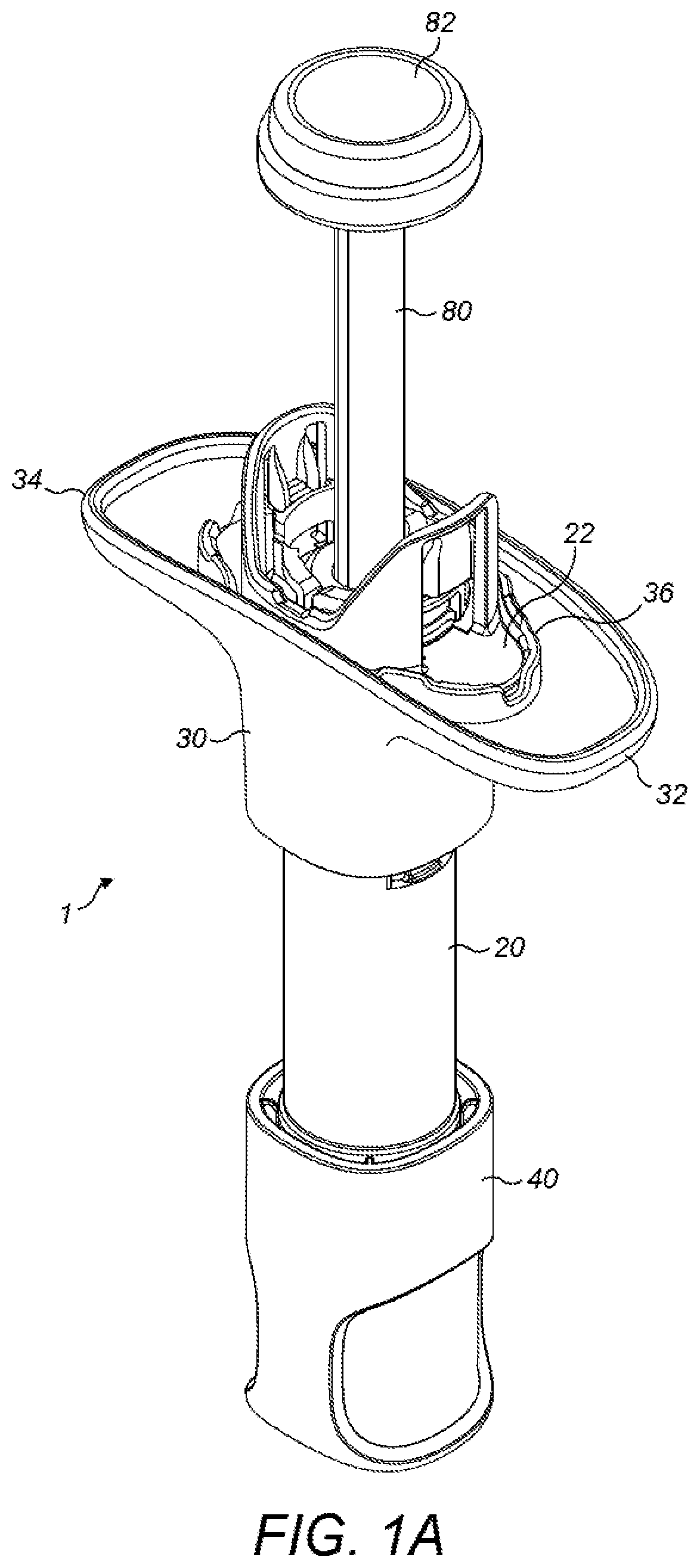
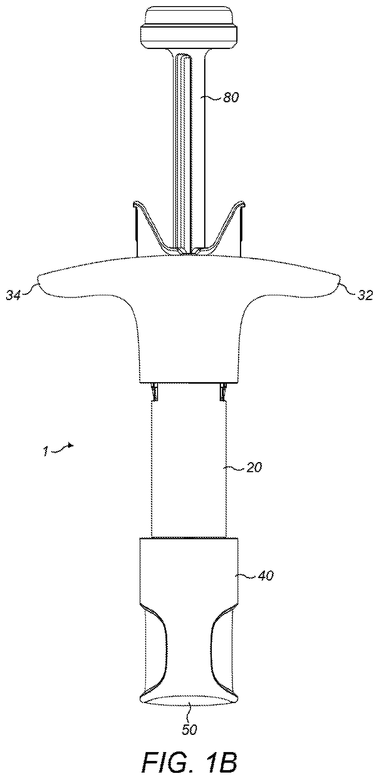
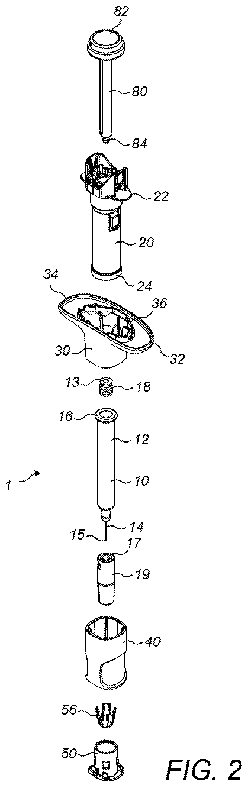
[0117]Referring now to the drawings, FIGS. 1A, 1B and 2 show aspects of a manual injector 1 herein, which is arranged for use with a syringe 10 that contains a liquid drug formulation. FIGS. 1A and 1B shows the injector 1 in a capped (pre-use) configuration and FIG. 2 shows an exploded view of the injector. The injector 1 comprises a generally cylindr...


PUM


Abstract

Provided is a cap for an injector comprising a syringe with a needle cover. The cap comprises a cap body defining an inner and outer cap body; provided to the inner cap body, a grip for gripping the needle cover of said syringe; provided to the outer cap body, an opposing pair of recessed portions, wherein each recessed portion defines a recess base, and wherein each recessed portion is bounded by a peripheral lip; and provided to the recess base of each recessed portion, an over-coating. The cap body comprises a generally rigid material and each over-coating comprises a more flexible material. Each peripheral lip defines banks that extend beyond the over-coating of the recess base.

Description

BACKGROUND[0001]The present invention relates to a cap for an injector device for receipt of a syringe that is suitable for use in the injected delivery of a liquid drug formulation to a patient.[0002]It is well-known to use syringes for the delivery of injectable liquid drug formulation to a patient. Syringes rely on puncturing of the patient's skin by a hollow needle through which the injectable liquid drug (e.g. in solution or suspension form) is delivered to the muscle or tissue of the patient. Typically, syringes comprise a barrel for containing a volume of the liquid drug; a hollow needle defining a needle tip for dispensing of the liquid; and a plunger that is axially movable within the barrel.[0003]It is also well-known to provide injectors for use with syringes. Such injectors typically comprise a housing comprising one or more housing parts for housing the syringe and an actuating mechanism, which is actuable in use, to allow for delivery of the liquid drug formulation fro...

Claims


Application Information

Patent Timeline
Patent Type & Authority Applications(United States)
IPC IPC(8): A61M5/32
CPCA61M2205/0216A61M5/3257A61M5/3204A61M5/3202A61M5/326A61M2005/3263A61M2005/3264
Inventor KNIGHT, BARRY ALANPLEVNIK, MARKOINOUE, NORIHIKOBUCKLEY, JAMIEHORNSEY, LISA
Owner UCB PHARMA SRL
Why Eureka
Try Eureka