
Door locking system

a technology of locking system and door, applied in the direction of glass wings, doors/windows, building components, etc., can solve the problems of poor durability and decrease in construction work ability, and achieve the effect of improving construction work ability, improving durability, and simplifying the assembling and disassembling process

Inactive Publication Date: 2020-10-01
CHOI YOUNGJAE
View PDF0 Cites 2 Cited by
  • Summary
  • Abstract
  • Description
  • Claims
  • Application Information

AI Technical Summary

Benefits of technology

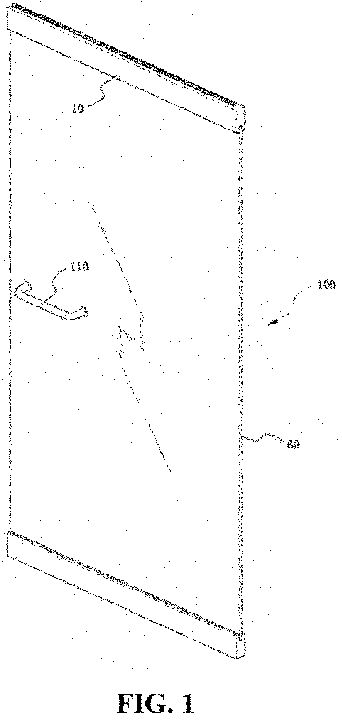
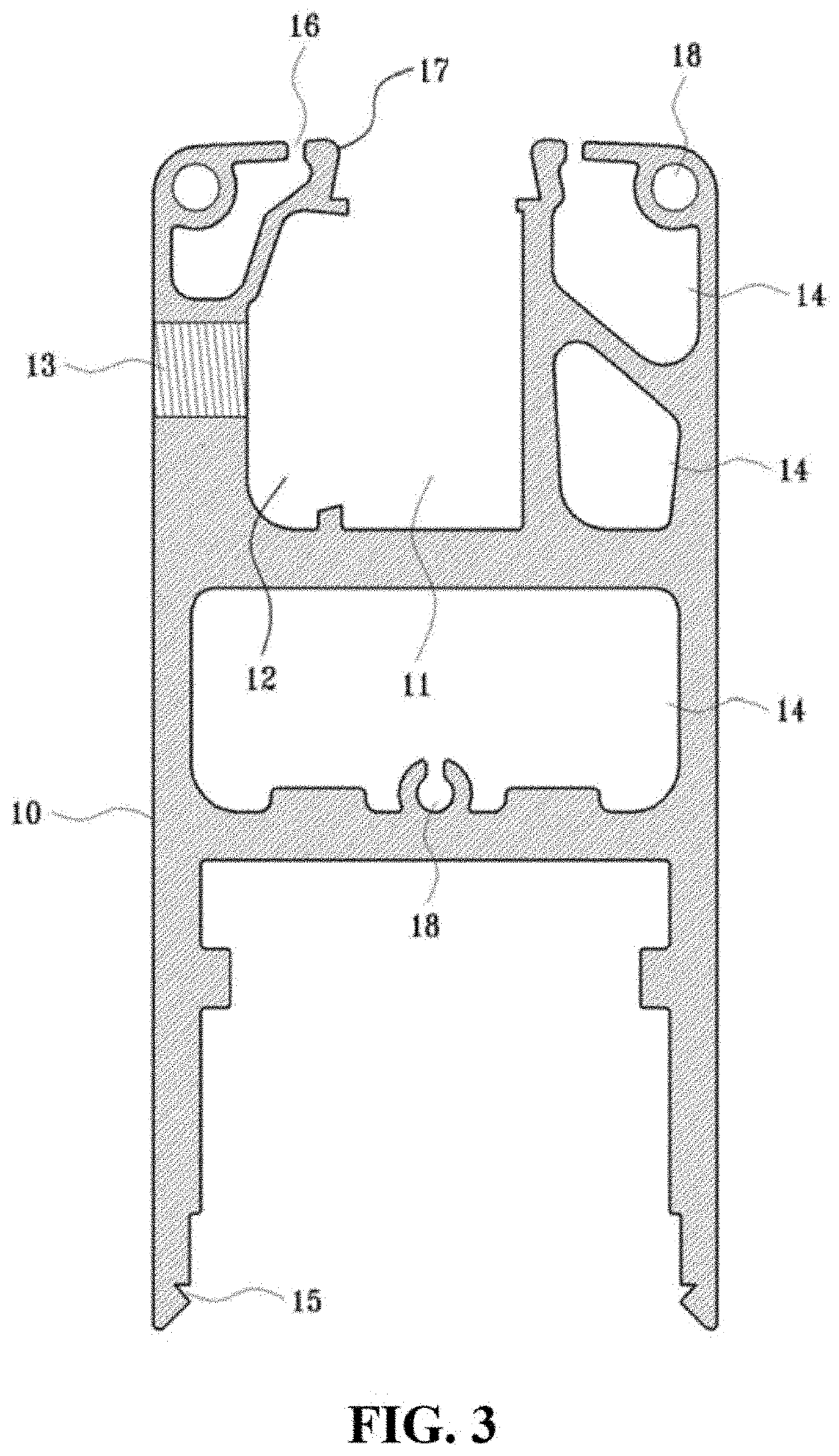
The present invention provides a door locking system for tempered glasses that solves problems in conventional door fixing systems. The system includes a frame, a captive bolt, and a stopper, which is set in the frame and a tempered glass is inserted into the hole of the frame. The captive bolt is tightened to keep pressing the tempered glass, which comes into close and tight contact with the frame, for increased durability and simplified construction work ability. The invention also provides a easier installation work at the door entrance based on the bottom surface of the entrance and the slope of the door frame.

Problems solved by technology

However, the conventional technology has defects of poor durability because its tempered glass is not fixed firmly to its upper and lower frames, and furthermore, its installation work in the location is very difficult to meet the inclined slope of the door frame in relation to the bottom surface of the entrance in the installation location, and the construction work ability is decreased because its assembling and disassembling was complicated.

Method used


Image

  • Door locking system
  • Door locking system
  • Door locking system

Examples


Embodiment Construction

[0037]Since exemplary embodiments of the present invention are provided only for structural and functional descriptions of the present invention, the present invention should not be construed as limited to the embodiments set forth herein. Thus, it will be clearly understood by those skilled in the art that the exemplary embodiments of the present invention may be embodied in different forms and include equivalents that can realize the spirit of the present invention. It should be understood, however, that it is not intended to limit the present invention to the particular forms disclosed, but on the contrary, the present invention is to cover all modifications, equivalents, and alternatives falling within the spirit and scope of the present invention as defined by the appended claims.

[0038]It will be understood that when an element or part is referred to as being “connected to” or “coupled to” another element or part, it can be directly connected or coupled to the other element or ...


PUM

PropertyMeasurementUnit
pressureaaaaaaaaaa
durabilityaaaaaaaaaa
energy efficiencyaaaaaaaaaa

Abstract

Provided is a door locking system including: a frame (10) including a hole (11) and a stopper hole (12), wherein the hole (11) is formed inside the frame (10), wherein a door glass (60) is fitted in the hole (11, wherein the stopper hole (12) is recessed from the hole (11) into a first sidewall of the frame (10); a captive bolt (20) inserted into the first sidewall of the frame (10) in a first direction toward the stopper hole (12); and a stopper (30) fitted in the stopper hole (12), wherein the second direction is perpendicular to the first direction.

Description

CROSS-REFERENCE TO RELATED APPLICATION[0001]This application claims priority under 35 U.S.C. § 119 to Korean Patent Application No. 10-2019-0037646 filed on Apr. 1, 2019, the disclosure of which is hereby incorporated by reference in its entirety.FIELD OF INVENTION[0002]Embodiments of the present invention relate to a technology about tempered glass doors installed in the entrances of houses or buildings, and more particularly, to a door locking system for fixing a glass to a frame tightly and strongly by providing a stopper to the frame and putting a captive bolt to the frame, and setting a tempered glass into a hole of the frame and tightening the captive bolt for the stopper to be pressed against the tempered glass such that the tempered glass can contact the frame closely and can be fixed to the frame tightly and safely, thereby to improve the durability of the tempered glass and the frame further and make their assembling and disassembling easier and enhance the construction an...

Claims


Application Information

Patent Timeline
Patent Type & Authority Applications(United States)
IPC IPC(8): E06B3/58E06B7/18E06B3/02E06B3/28E06B3/60
CPCE06B3/5871E06B7/18E06B3/28E06B3/02E06B3/605E06B3/305E06B3/5454
Inventor CHOI, YOUNGJAE
Owner CHOI YOUNGJAE
Learn More