
Energy absorbing beam

a beam and energy technology, applied in the field can solve the problems of inability to adapt to other applications, inability to meet the needs of other applications, etc., and achieve the effect of reducing the number of energy absorbing beams

Active Publication Date: 2020-10-01
GM GLOBAL TECH OPERATIONS LLC
View PDF0 Cites 0 Cited by
  • Summary
  • Abstract
  • Description
  • Claims
  • Application Information

AI Technical Summary

Benefits of technology

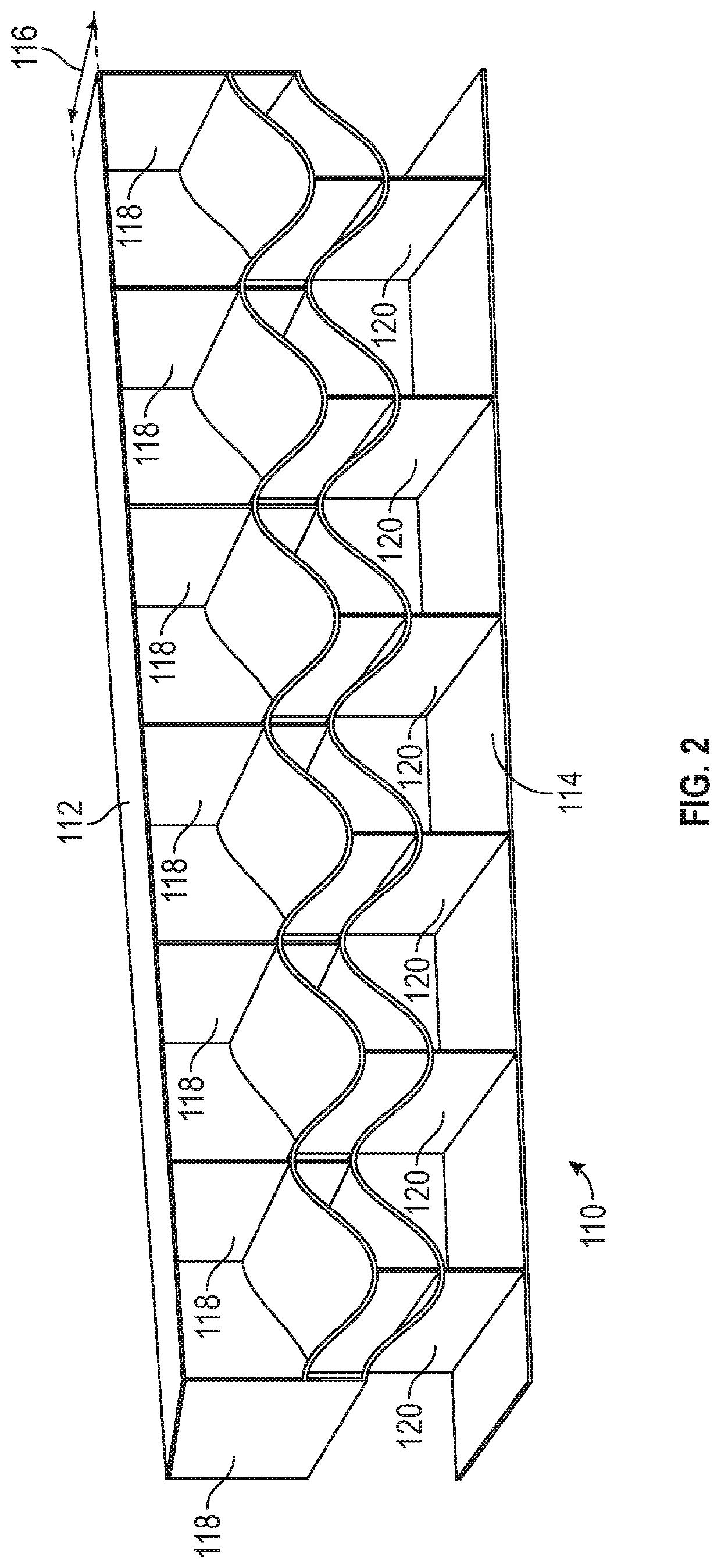
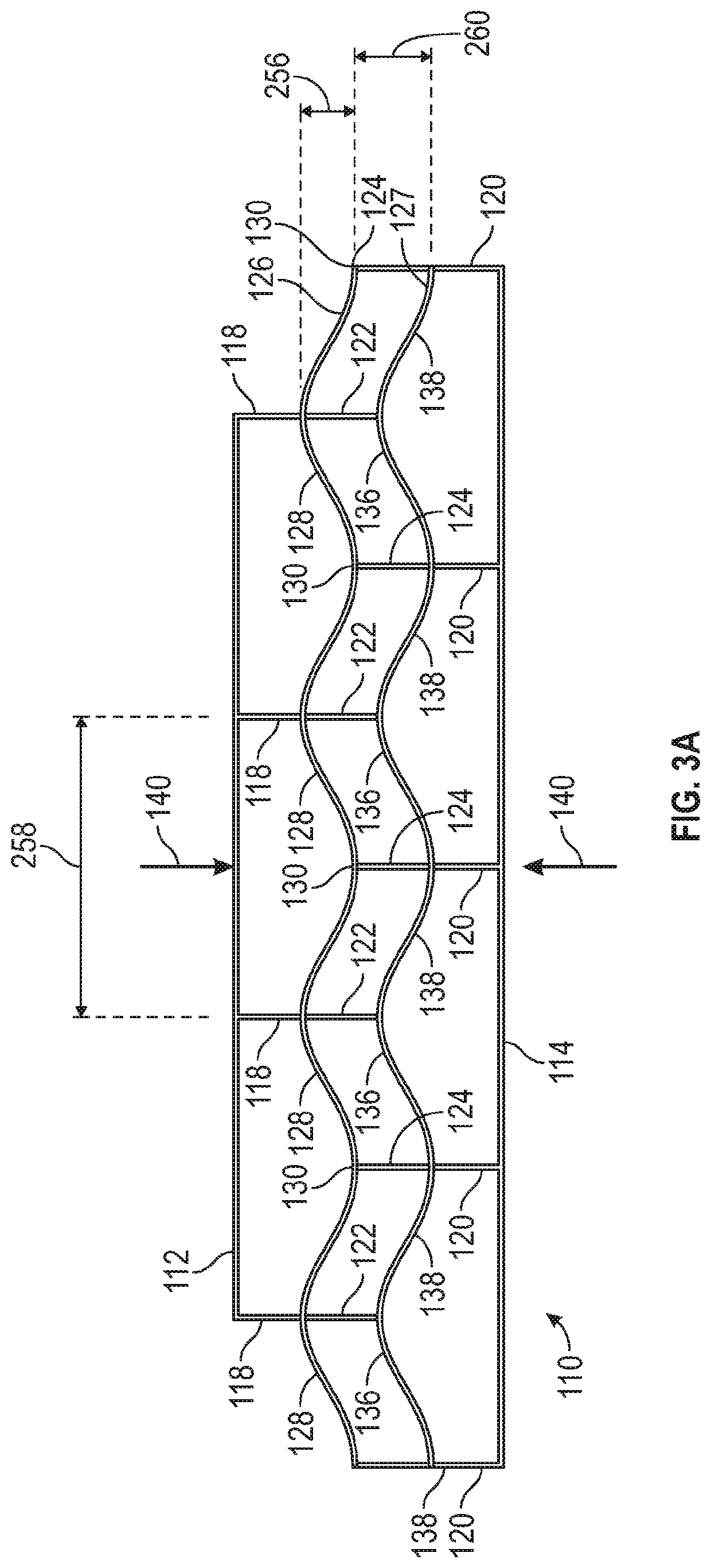
The present disclosure relates to an energy absorbing beam that can be used in many applications to absorb energy. For example, in automobiles, the energy absorbing structure can provide a crumple zone to protect passengers in the event of a crash. The patent text describes how the beam bends due to the compression between upper and lower pillars, which prevents lateral expansion of the beam. This design can effectively absorb energy and minimize injury to passengers in a crash.

Problems solved by technology

Existing energy absorbing structures have limitations.
They are not adjustable to be suitable for other applications.
Additionally, existing energy absorption structures sometimes rely on catastrophic failure of the structure to absorb energy.
Energy absorbing structures that fracture under impact are difficult to control, which makes it difficult to predict how the structure will react to an impact.

Method used


Image

  • Energy absorbing beam
  • Energy absorbing beam
  • Energy absorbing beam

Examples


Embodiment Construction

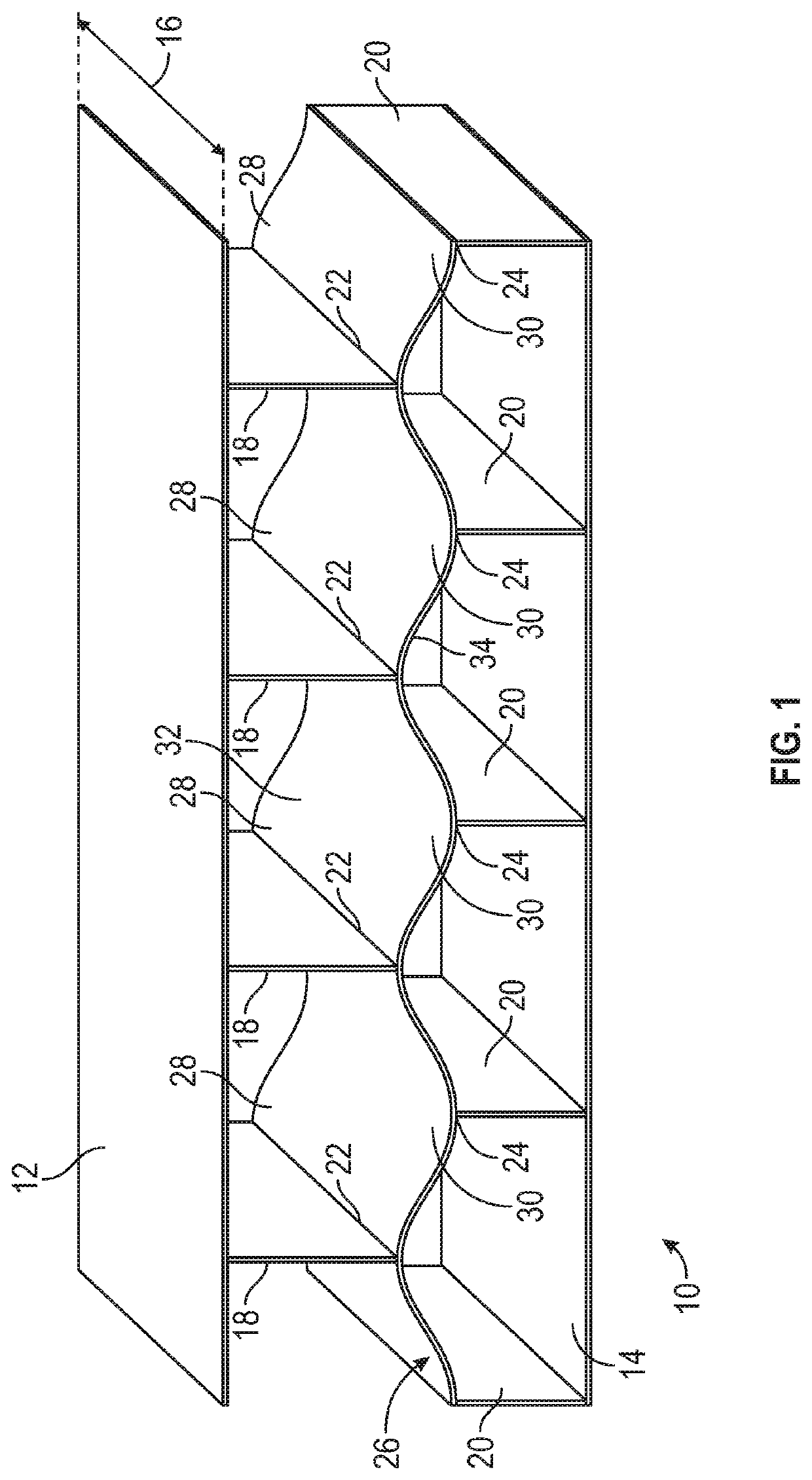
[0032]The following description is merely exemplary in nature and is not intended to limit the present disclosure, application, or uses. Referring to FIG. 1, an energy absorbing beam, according to an exemplary embodiment is shown generally at 10. The energy absorbing beam 10 comprises a top plate 12 and a bottom plate 14. The top plate 12 and bottom plate 14 are lie in parallel horizontal planes spaced apart from one another. The top plate 12 and bottom plate 14 define a width 16 of the energy absorbing beam 10.

[0033]A plurality of upper pillars 18 extend from the top plate 12 toward the bottom plate 14 and a plurality of lower pillars 20 extends from the bottom plate 14 upwards toward the top plate 12. The plurality of upper pillars 18 are spaced uniformly along the top plate 12. Each of the plurality of upper pillars 18 extends vertically straight downward toward the bottom plate 14, perpendicular to the top plate 12, along the entire width 16 of the energy absorbing beam 10. Each...


PUM


Abstract

An energy absorbing beam comprises a top plate and a bottom plate, a plurality of upper pillars extending from the top plate toward the bottom plate, a plurality of lower pillars extending from the bottom plate toward the top plate, and a first beam extending laterally between the top plate and the bottom plate and attached to the upper and lower pillars, wherein energy from an impact onto the top or bottom plate is transferred through the upper and lower pillars and absorbed by the first beam.

Description

INTRODUCTION[0001]The present disclosure relates to an energy absorbing beam. Energy absorbing structure is used in many applications where absorption of energy is needed. For instance, within an automobile, energy absorbing structure provides a crumple zone to absorb the energy of a crash. This helps to cushion the passengers within the automobile and prevent injury in the event of a crash.[0002]Existing energy absorbing structures have limitations. For example, existing energy absorbing structures are designed for a specific application and may only be suitable for that particular application. They are not adjustable to be suitable for other applications. Additionally, existing energy absorption structures sometimes rely on catastrophic failure of the structure to absorb energy. Energy absorbing structures that fracture under impact are difficult to control, which makes it difficult to predict how the structure will react to an impact.[0003]Thus, while current energy absorbing str...

Claims


Application Information

Patent Timeline
Patent Type & Authority Applications(United States)
IPC IPC(8): F16F7/12
CPCB62D21/15F16F2234/06F16F7/128B62D25/00F16F7/122
Inventor MISHRA, DEVANJAN
Owner GM GLOBAL TECH OPERATIONS LLC
Learn More