Lens unit

a technology of lens and holder, applied in the field of lens units, can solve the problems of caulking part tip end side damage, etc., and achieve the effect of enhancing the waterproof performance between the first lens and the holder

Active Publication Date: 2020-10-01
SANKYO SEIKI MFG CO LTD
View PDF0 Cites 2 Cited by
  • Summary
  • Abstract
  • Description
  • Claims
  • Application Information

AI Technical Summary

Benefits of technology

[0020]In the lens unit in accordance with the present invention, a side face of the first lens is provided with a third side face part between a first side face part, which is extended from an outer edge of an object side face (first face) of the first lens toward an image side, and a second side face part which is extended from the object side toward the image side on the image side with respect to the first side face part and on an outer side in the radial direction with respect to the first side face part. Further, the holder is provided with a caulked part which covers the third side face part from the object side at an object side end part of the first lens holding tube part surrounding a periphery of the second side face part. An inner side end part in the radial direction of the caulked part is located on the image side with respect to a virtual extended face which is obtained by extending the first face to an outer side in the radial direction. Therefore, when a high pressure water flow is ejected to the first lens from the object side, the water flow flows to an outer side in the radial direction along the first lens face and the virtual extended face and thus, a situation is hard to occur that the water flow hits the inner side end part in the radial direction of the caulked part from an inner side in the radial direction with strong pressure. Accordingly, water is hard to enter between the side face of the first lens and the first lens holding tube part of the holder. Further, deformation to an outer side in the radial direction and damage due to water pressure are hard to occur in the inner side end part in the radial direction of the caulked part. Therefore, waterproof performance between the first lens and the holder can be enhanced.

Problems solved by technology

However, when a high pressure water flow is ejected to the first lens 11 from the object side “La”, there is a problem that a tip end side of the caulked part 78 may be damaged by the water pressure and water is easily entered from a space between the first lens 11 and the caulked part 78.

Method used


Image

  • Lens unit
  • Lens unit
  • Lens unit

Examples


first embodiment

(Structure of Lens Unit)

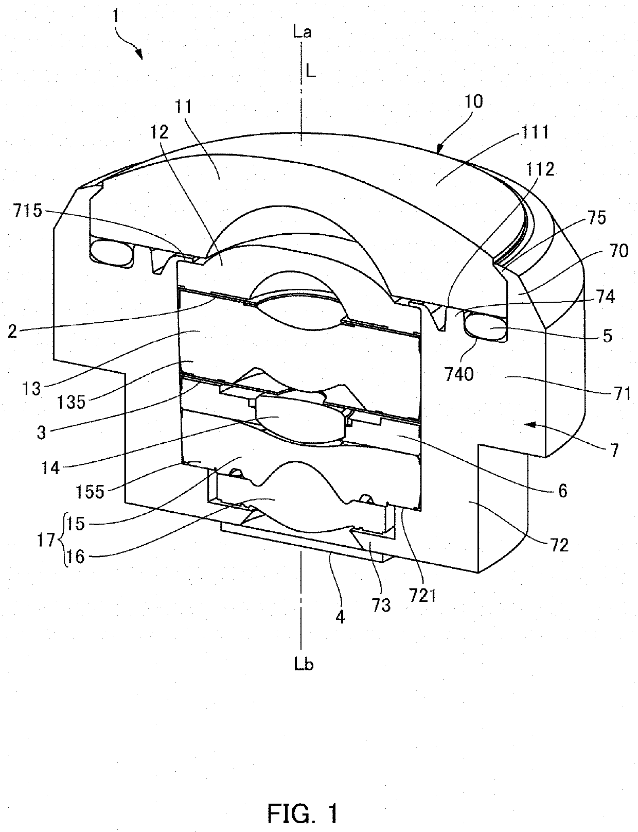
[0030]FIG. 1 is a perspective view showing a lens unit 1 in accordance with a first embodiment of the present invention in which a part of the lens unit 1 is cut out and viewed from an object side. As shown in FIG. 1, a lens unit 1 in this embodiment includes a wide-angle lens 10 comprised of a plurality of lenses disposed in an optical axis “L” direction and a tube-shaped holder 7 which holds the wide-angle lens 10 on an inner side, and the lens unit 1 is used in an optical device such as an imaging device. In this embodiment, the holder 7 is made of light shielding resin.

[0031]The wide-angle lens 10 has, for example, a 5-group 6-piece lens configuration. More specifically, the wide-angle lens 10 is, from the object side “La” (object to be photographed side / front side) toward the image side “Lb”, configured of a first lens 11 having negative power, a second lens 12 having negative power, a third lens 13 having positive or negative power, a fourth lens 14 hav...

second embodiment

[0047]FIG. 4 is an enlarged cross-sectional view showing surroundings of a caulked part 75 to a first lens 11 of a lens unit 1 in accordance with a second embodiment of the present invention. In each of this embodiment and embodiments described below, basic configurations are the same as each other and thus, the same reference signs are used in common portions and their descriptions are omitted.

[0048]In the first embodiment, the protruded part 751 formed in the inner side end part 750 in the radial direction of the caulked part 75 is extremely thin in comparison with the other portion of the caulked part 75. However, as shown in FIG. 4, a configuration may be adopted that a protruded part 751 is comparatively thick and an outer peripheral face of the protruded part 751 is formed to be an inclined face. Also in this case, the protruded part 751 is located on the image side “Lb” with respect to a virtual extended face “S” which is obtained by extending an object side “La” face (first ...

third embodiment

[0049]FIG. 5 is an enlarged cross-sectional view showing surroundings of a caulked part 75 to a first lens 11 of a lens unit 1 in accordance with a third embodiment of the present invention. In the first and second embodiments, the inner side end part 750 in the radial direction of the caulked part 75 covers the first side face part 116 from an outer side in the radial direction. However, as shown in FIG. 5, an inner side end part 750 in the radial direction of a caulked part 75 may be located at a position separated toward an outer side in the radial direction from a first side face part 116. Also in this embodiment, the inner side end part 750 in the radial direction of the caulked part 75 is located on the image side “Lb” with respect to a virtual extended face “S” which is obtained by extending a first face 111 to an outer side in the radial direction. Therefore, similar effects to the first embodiment are attained, for example, when a high pressure water flow “W” is ejected to ...


PUM


Abstract

A lens unit may include lenses and a holder in a tube shape which holds the lenses on an inner side such that in the lenses, a side face of a first lens located on a most object side may include a first side face part which is extended from an outer edge of a first face that is an object side face of the first lens toward an image side, a second side face part which is extended from an object side toward the image side on the image side with respect to the first side face part and an outer side in a radial direction with respect to the first side face part; and a third side face part which connects an image side end part of the first side face part with an object side end part of the second side face part.

Description

CROSS REFERENCE TO RELATED APPLICATION[0001]This is the U.S. national stage of application No. PCT / JP2018 / 033539, filed on Sep. 11, 2018. Priority under 35 U.S.C. § 119(a) and 35 U.S.C. § 365(b) is claimed from Japanese Patent Application No. 2017-189367, filed on Sep. 29, 2017; the disclosures of which are incorporated herein by reference.TECHNICAL FIELD[0002]The present invention relates to a lens unit in which a plurality of lenses is held by a holder.BACKGROUND ART[0003]In a lens unit in which a plurality of lenses is accommodated in a holder made of resin, as shown in FIG. 8, a structure is sometimes adopted that, in the plurality of lenses such as a first lens 11 and a second lens 12, a seal member 5 is disposed between the first lens 11 located on the most object side “La” and the holder 7. Further, a structure is sometimes adopted that the holder 7 is provided with a first lens holding tube part 70 surrounding a periphery of the first lens 11 on an object side “La” with resp...

Claims


Application Information

Patent Timeline
Patent Type & Authority Applications(United States)
IPC IPC(8): G03B17/08G02B9/62G02B7/02
CPCG03B17/08G02B7/021G02B9/62G02B7/026G02B7/025G02B7/007G02B7/022
Inventor SHIROTORI, TOSHIONAKAJIMA, TOMOAKI
Owner SANKYO SEIKI MFG CO LTD
Why Eureka
Try Eureka