Construction and monitoring of barrier walls

a technology for building walls and barriers, applied in the field of building systems, can solve the problems of increasing construction costs and difficulty in building walls such as barriers with concr

Active Publication Date: 2020-10-08
CONSULTING ENGINEERS CORP
View PDF0 Cites 0 Cited by
  • Summary
  • Abstract
  • Description
  • Claims
  • Application Information

AI Technical Summary

Benefits of technology

[0008]The present invention provides for a barrier wall with a front wall extending upwardly which acts as a barrier between two regions. Buttress walls extending from the rear side of the front wall. The buttress walls provide for lateral support for the front wall. The plurality of Buttress walls are spaced specific distances and provides the 3-Dimensional approach for the load transfer. Horizontal decks positioned between the buttress wall layers. The horizontal decks are positioned at half or a third the height of the front wall. Additional horizontal decks are positioned three quarters or seven eighths of the total height of front wall. Horizontal deck provides the lateral stability by providing the diaphragm action for horizontal load transfer.

Problems solved by technology

However, the 2-Dimensional approach for the wall design increases the construction cost due to thicker wall sections by using traditional design approach.
This provides for a diverse number of issues if the wall design is not able to be built through uneven terrain or around various obstacles.
Construction of the walls such as a barrier wall with concrete has the challenge due to the difficult terrain and the geometry of the structure.
Another issue is the length of ground which the wall is to cover may require constant maintenance after the wall is constructed, this would require a modular design to allow for work on specific sections of the wall without affecting the other portions of the wall.

Method used


Image

  • Construction and monitoring of barrier walls
  • Construction and monitoring of barrier walls
  • Construction and monitoring of barrier walls

Examples


Embodiment Construction

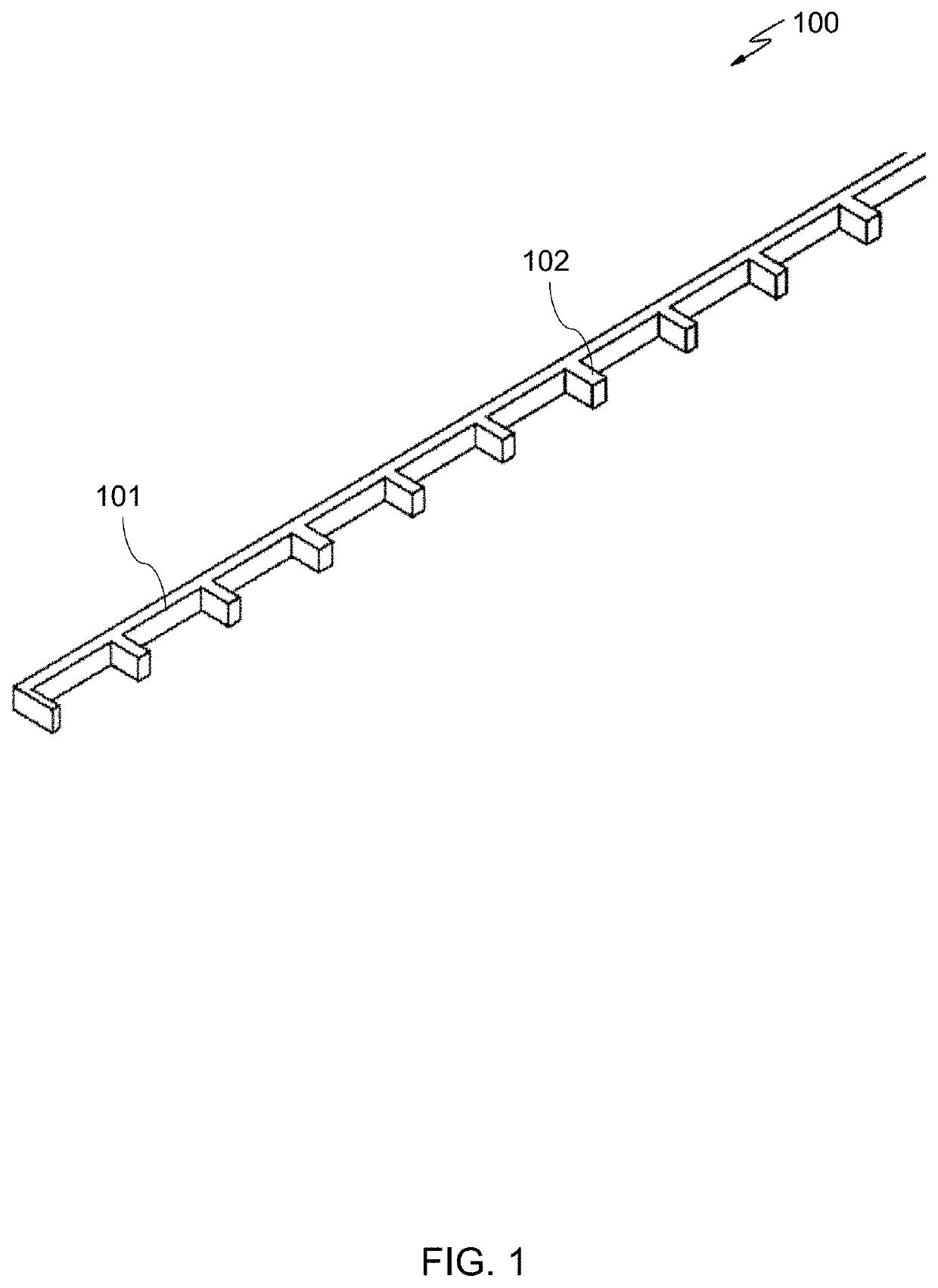
[0030]The present invention provides for the method of construction a barrier wall and the barrier wall, wherein the barrier wall is designed for an optimized wall height, spacing between buttress and spacing between horizontal deck which results in minimum use of material, provide for a simplified and uniform construction process, and thus a reduction in cost for construction. By uniquely changing the approach from traditional 2-Dimensional design approach to a Multi-Dimensional design, the wall design results in reduction of materials required and also reduce the foundation design requirements in the Multi-Dimensional load transfer as compared to 2-Dimensional load transfer. Different structural elements are put to optimum use in multi-dimensional approach.

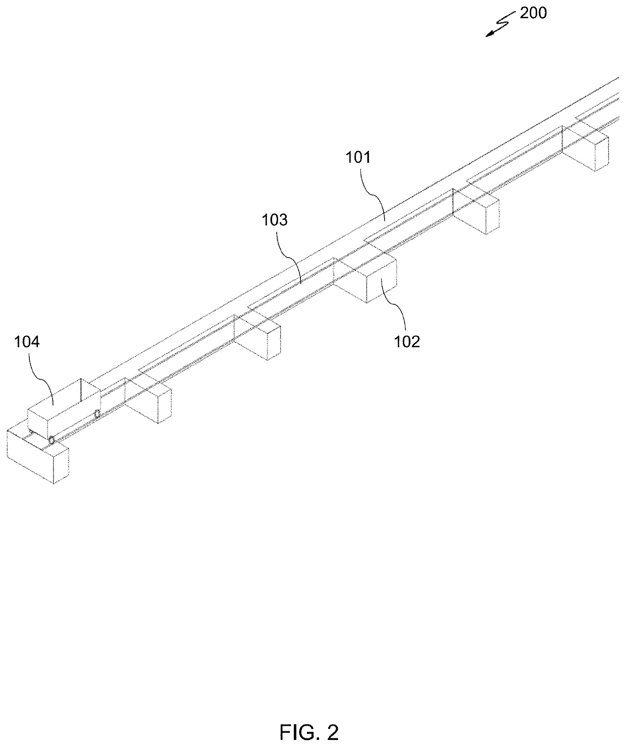
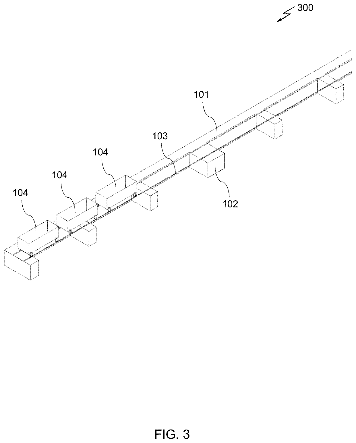
[0031]Present invention simplifies the construction process for barrier wall where the progressive construction of the barrier wall is done with the wagons travelling over the Rails. Rails are resting on the Foundation for the b...


PUM


Abstract

The present invention is a barrier wall comprising: a foundation, wherein the foundation has a plurality of extensions protruding from one side of the foundation; a set of lower buttress walls positioned along each of the extensions; a first deck positioned on the first set of lower buttress walls; a set of upper buttress walls positioned along the decks upper surface; a second deck positions on the second set of upper buttress walls; and a front wall positioned to substantially cover the set of lower buttress walls, the lower deck, the set of upper buttress walls, and the upper deck.

Description

CROSS-REFERENCE TO RELATED APPLICATIONS[0001]This application is a continuation- (and claims the benefit of priority under 35 USC 120) of U.S. application No. 62 / 827,874 filed Apr. 2, 2019 currently pending. The disclosure of the prior applications is considered part of (and is incorporated by reference in) the disclosure of this application.BACKGROUND OF THE INVENTION[0002]The present invention relates to a building system, and more particularly to the building process of a wall for security purposes.[0003]Border and / or security walls are critical for engineering design because of its Geometry and location. Example is the barrier wall along the United States and Mexico border which is a nationwide topic of discussion. However, the 2-Dimensional approach for the wall design increases the construction cost due to thicker wall sections by using traditional design approach.[0004]Additionally, with the length of a barrier wall there is a variety of terrain, unlevel terrain, and various ...

Claims


Application Information

Patent Timeline
Patent Type & Authority Applications(United States)
IPC IPC(8): E04B1/04E02D27/32
CPCE04B1/04E02D27/32
Inventor JALLA, MAHARAJ K.
Owner CONSULTING ENGINEERS CORP
Why Eureka
Try Eureka