Leveling foot

a leveling foot and foot technology, applied in the field of self-adjusting leveling feet, can solve the problems of increasing the weight of the structure, affecting the stability of the foot, so as to achieve the effect of stable support and easy removal

Active Publication Date: 2019-05-16
AUTOSTORE TECH AS
View PDF31 Cites 3 Cited by
  • Summary
  • Abstract
  • Description
  • Claims
  • Application Information

AI Technical Summary

Benefits of technology

[0011]The movable top piece, according to one aspect of the invention, has structures designed to securely engage the underside of the structure to be leveled, for example a support leg of a storage grid. In one embodiment, the top piece has a raised protrusion that mates with a corresponding opening at the bottom of a leg. The top piece, in this preferred embodiment, is further provided with upwardly projecting wings that engage on the outside of the leg to provide lateral stability. It is to be understood, however, that other arrangements are possible for secure engagement of the movable top piece with the structure to be leveled. For example, the top piece could be provided with guide pins that engage guide holes underneath a structure to be leveled. The top piece could be provided with grooves or ridges that slidably engage corresponding grooves or ridges underneath the structure to be leveled, or the top piece could an integrated portion of the underside of the structure.
[0012]In use, a structure to be leveled is erected. A leveling foot according to the present invention is inserted at the corners or other appropriate locations. The top piece engages the underneath of the structure and the spring causes the leveling foot to expand to fill any gap created by uneven flooring. When the structure is leveled, the U-shaped wedge device is inserted, and pressed forward until the upper surface of the legs of the wedge engage with the angled lower surfaces of the side walls of the movable top piece. The teeth of the wedge and the column lock the wedge in place. In the event the floor were to sink later in the life of the structure, the wedge device can simple be pressed further forward to again achieve a stable base of support. Given that the leveling foot is manufactured from a robust material, the leveling foot of the device can bear a substantial weight, as the side walls rest in a stable manner upon the wedge device. When removing the leveling foot, the wedge device can be easily removed by spreading apart the legs of the U-shaped device until the teeth no longer engage with the teeth of the column.

Problems solved by technology

The problem is exacerbated when the floor on which the structure is installed is uneven.
In cases where the structure is particularly heavy, a structure that is initially level may, do to the weight of the structure, become unlevel over time.
A disadvantage to such thread-based solutions is that the threads of the foot must bear the weight of the structure.
This may lead to device failure where the structure is very heavy.
A simple wedge, however, is not self-adjusting and can be difficult or impossible to remove once the weight of the structure bears down upon the wedge.
While this device has the advantage of being self adjusting during installation, it suffers from the disadvantage of using a thin shaft to bear the weight of the structure, which can lead to failure when the structure is particularly heavy.

Method used


Image

  • Leveling foot
  • Leveling foot
  • Leveling foot

Examples


Embodiment Construction

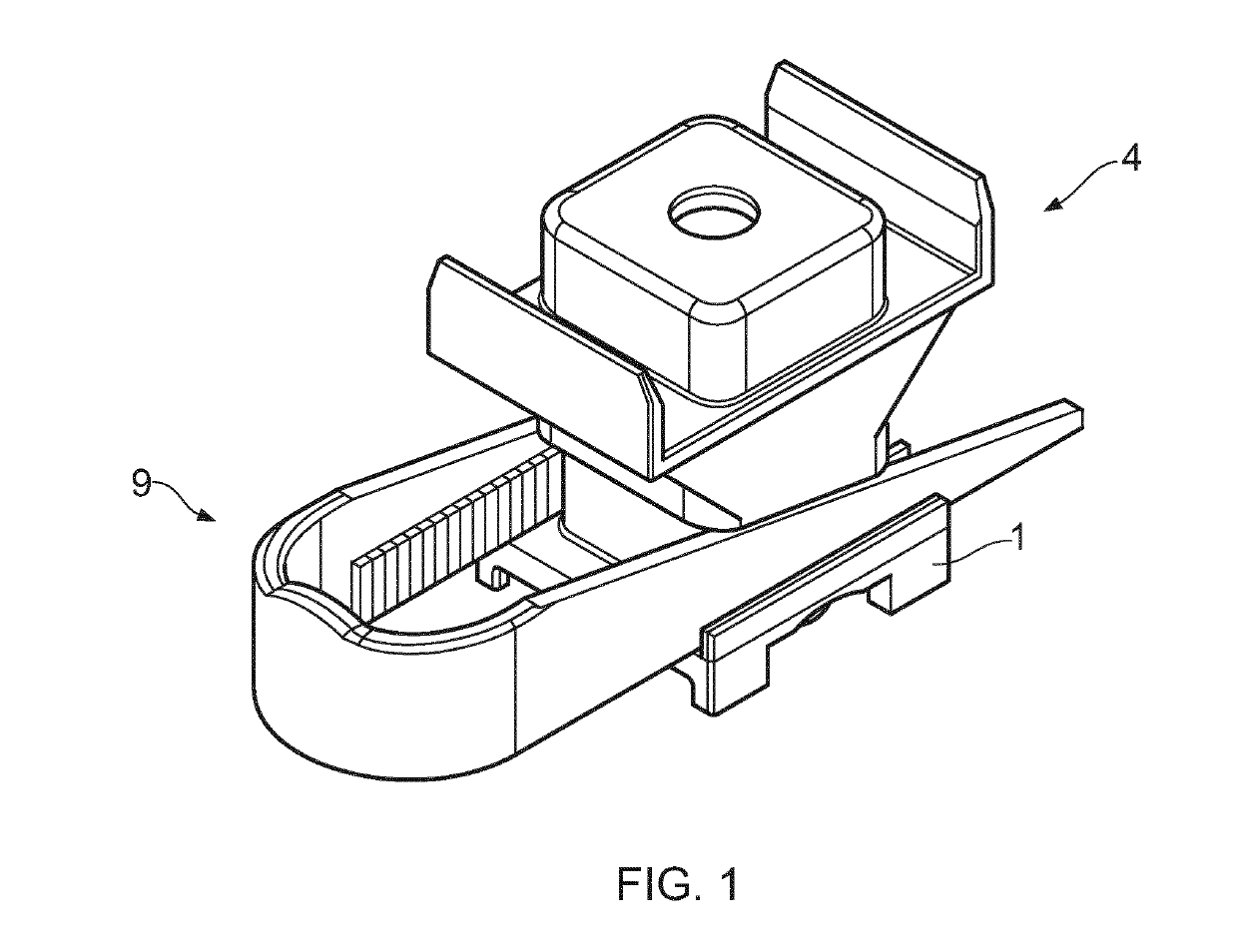
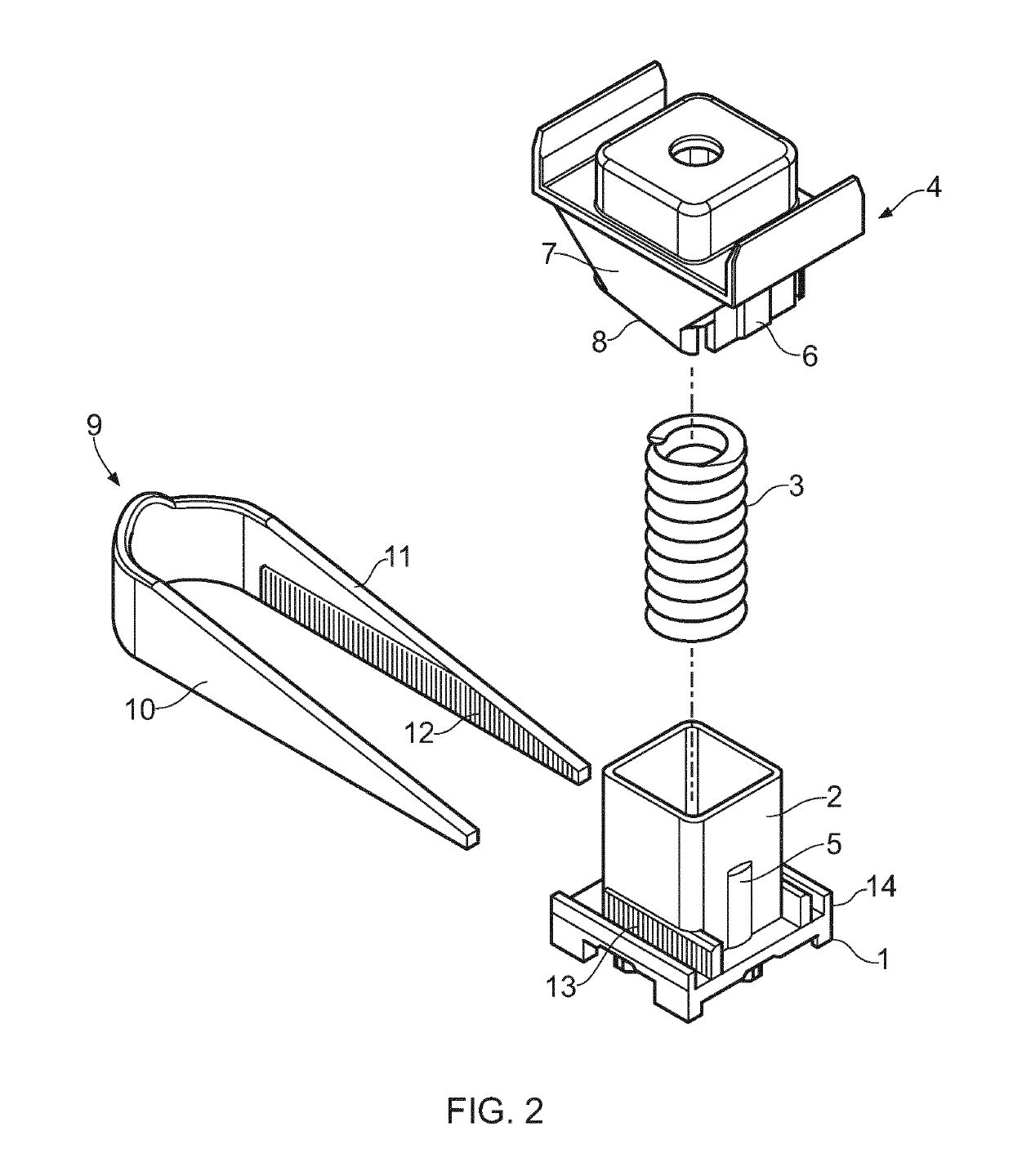
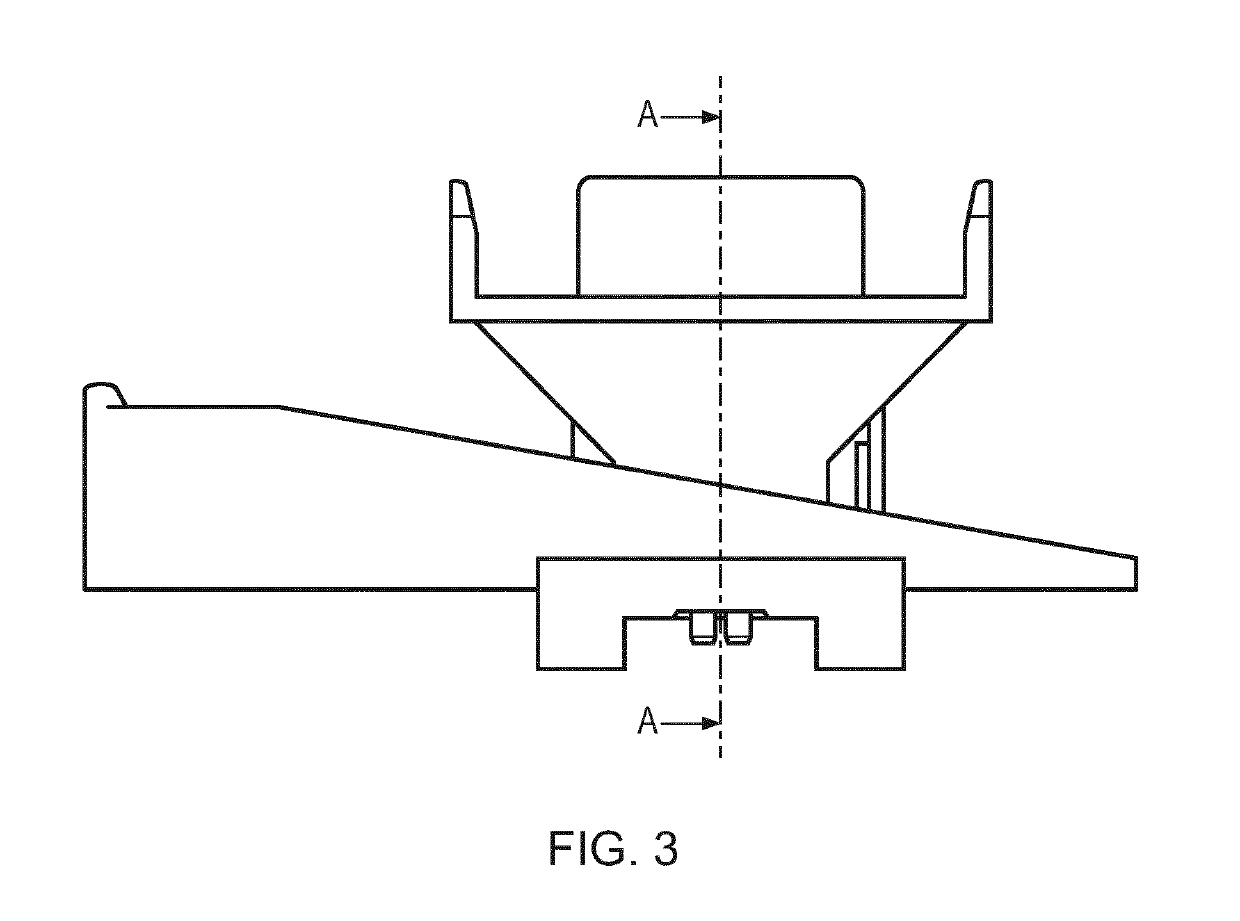
[0020]As shown in FIGS. 1 and 2, the leveling foot of the invention comprises base section 1. In a preferred embodiment illustrated, the base section has a rectangular or square profile, but other shapes are possible within the scope of the invention. A hollow column 2 extends upwards from the base 1. A spring 3 is arranged in the hollow column 2. A movable top piece 4 is arranged about column 2. Top piece 4 is slightly larger than column 2 such that column 2 extends into a recess in top piece 4 when the top piece is pressed down against the resistance from spring 3. According to one aspect, column 2 has a guide ridge 5 that engages a guide recess 6 on top piece 4.

[0021]Top piece 4 has one or more side walls 7. The lower surface of guide wall 7 has an angled edge 8. The leveling foot further comprises a generally U-shaped wedge piece 9 with two legs 10. Legs 10 have an angled, upper surface 11, the angle of which corresponds to the angle of edge 8 of top piece 4. Along the inner sur...


PUM


Abstract

A leveling foot having a base section with a raised, hollow column. A spring is arranged in the hollow column. A moveable top piece engages the column, and is movable in the vertical direction against the force of the spring. The top piece is slightly larger than the column, such that side walls of the top piece overlap the sides of the column when the spring is compressed. The bottom edges of the side walls of the top piece are angled. A generally U-shaped wedge device is provided that may be pressed into engagement with the base section, whereby a leg of the U engages each side of the column. The top surfaces of the legs of the U-shaped device are angled in the form of wedges, the angles of the top surfaces of the legs corresponding to the angles of the side walls of the movable top piece, such that the side walls of the top piece will rest upon the angled top surfaces of the legs of the wedge device when the top piece is under load.

Description

FIELD OF THE INVENTION[0001]The present invention relates to a leveling device, more particularly to a self-adjusting leveling foot for a storage grid or similar structures.BACKGROUND OF THE INVENTION[0002]There are many situations where it is necessary for a storage system, machine or other type of structure to be level. The problem is exacerbated when the floor on which the structure is installed is uneven. In cases where the structure is particularly heavy, a structure that is initially level may, do to the weight of the structure, become unlevel over time. It is therefore advantageous to provide a leveling foot under the structure that can be adjusted to achieve a level installation.[0003]A known solution to the problem is to provide an adjustable foot of the type having a threaded shaft that can be extended or retracted to compensate for an uneven floor. Such solutions are well known in common household appliances, and can be illustrated by the device shown in U.S. Pat. No. 3,4...

Claims


Application Information

Patent Timeline
Patent Type & Authority Applications(United States)
IPC IPC(8): A47B91/02F16M7/00
CPCA47B91/02F16M7/00A47B91/16
Inventor HOGNALAND, INGVARFJELDHEIM, IVARAUSTRHEIM, TRONDBEKKEN, BORGE
Owner AUTOSTORE TECH AS
Why Eureka
Try Eureka