Method for fabricating an electromagnet

a technology of electromagnets and electromagnets, which is applied in the direction of magnets, manufacturing tools, magnetic bodies, etc., can solve the problems of significant time and labor expenditure, ineffective structure for intended purposes, and subject to the expense of repair or replacement, so as to reduce the cost and time involved, and the effect of being convenient to us

Inactive Publication Date: 2007-02-08
THE BOEING CO
View PDF20 Cites 2 Cited by
  • Summary
  • Abstract
  • Description
  • Claims
  • Application Information

AI Technical Summary

Benefits of technology

[0011] The electromagnetic clamp for a structure and associated clamping method of the present invention provide techniques for securely clamping a structure, such as a multiple layer structure. In addition, the clamp and method of the present invention provide techniques for clamping a structure, particularly proximate the location where an operation is to be performed, in such a way that an operation may be performed on the structure without the layers separating. The techniques provided by the present invention are effective and easy-to-use, which therefore reduces the cost and time involved in performing an operation on structures, as compared to conventional procedures.
[0014] In general, the smallest lateral dimension of the core of the electromagnet is chosen to maximize the flux density between the core and the clamping piece. As such, the smallest lateral dimension of the core of the electromagnet is typically greater than the distance between the clamping piece and the electromagnet. For instance, the smallest lateral dimension of the core may be at least three times the distance between the clamping piece and the electromagnet. The core and the clamping piece may be made of steel, but the core may be made of steel with a higher permeability than the steel of the clamping piece. The core also may be made of a steel having a higher saturation flux density than the steel of the clamping piece. The core also may define a longitudinal aperture, which may have a diameter that is less than ten percent of the area of the core. The longitudinal aperture may permit operations, such as drilling and / or fastener installation, to be performed on the structure through the electromagnet.
[0019] Thus, the electromagnetic clamp and method for clamping a structure of the present invention provide techniques for securely clamping structures, such as multiple layer structures, to prevent the layers of the structure from separating during an operation, while other aspects of the present invention provide a method for fabricating an electromagnet capable of creating the force necessary to securely clamp the structure. Due to the configuration of the core and coil of the electromagnet, it is capable of cooperating with a piece of ferrous material to create a significant amount of attractive force, even when there is a gap between the electromagnet and the ferrous material. In addition, the electromagnet securely clamps the structure proximate the location where the operation is to take place. The clamp and method of the present invention therefore provide a way to perform operations, such as drilling and fastener installation, on a structure, such as a multiple layer structure, that is more efficient, faster and less expensive than the conventional procedures utilized in performing such operations.

Problems solved by technology

In many industries, operations must be performed on structures, such as multiple layer structures, and problems arise if the multiple layers of the structure cannot be securely held together during the operation.
Thus, if burrs, debris and / or excessive sealant are present, then the layers cannot be properly fastened, and the layers may suffer corrosion, cracking and / or premature fatigue failure, which generally renders the structure ineffective for its intended purpose and, therefore, subject to the expense of repair or replacement.
In the aerospace industry, for example, a significant amount of time and labor is expended ensuring that the holes through the various layers of the aircraft structure are appropriately drilled, cleaned, sealed and fastened.
This can cause a gap to develop between a drilled layer and the next layer, particularly when the layers are a stack-up of thin material.
The gap between the layers causes burrs about the hole and debris is likely to gather between the layers.
Thus, once the holes are drilled, the layers must be disassembled, the burrs must be removed from the holes, and the debris must be cleaned from the surfaces of the layers, all of which is a time-consuming and labor intensive process.
Overall, this process is expensive, laborious, and time-consuming.
In addition, the integrity of the resulting holes depends upon the completion of many manual processes, which creates a risk that certain steps may be performed inadequately or completely overlooked.
For complex structures and structures that are not easily accessible, it is difficult if not impossible to utilize a clamp.
In addition, bulkheads, fittings and the like in the structure also interfere with the use of a clamp on the structure.
If any gap exists between a conventional electromagnet and the ferrous material, however, significant losses in the force between the electromagnet and the ferrous material result.
Conventional electromagnets, therefore, do not create enough force to securely clamp multiple layers of a structure together because the force between a conventional electromagnet and the piece of ferrous material is subject to the inverse square law, i.e., the force is proportional to the inverse square of the distance between the electromagnet and the piece of ferrous material.
If a 1 / 16-inch gap of air or any non-ferrous material is introduced between the electromagnet and the ferrous material, the force between the electromagnet and the ferrous material drops to 95 lbs., which is not a sufficient amount of force to securely clamp a multiple layer structure together.
Since the structures are often formed of a non-ferrous material, however, this marked decrease in the clamping force due to the gap created by the structure poses a significant limitation upon the use of electromagnets for clamping any type of structure, including multiple layer structures.

Method used


Image

  • Method for fabricating an electromagnet
  • Method for fabricating an electromagnet
  • Method for fabricating an electromagnet

Examples


Embodiment Construction

[0024] The present inventions now will be described more fully hereinafter with reference to the accompanying drawings, in which some, but not all embodiments of the invention are shown. Indeed, these inventions may be embodied in many different forms and should not be construed as limited to the embodiments set forth herein; rather, these embodiments are provided so that this disclosure will satisfy applicable legal requirements. Like numbers refer to like elements throughout.

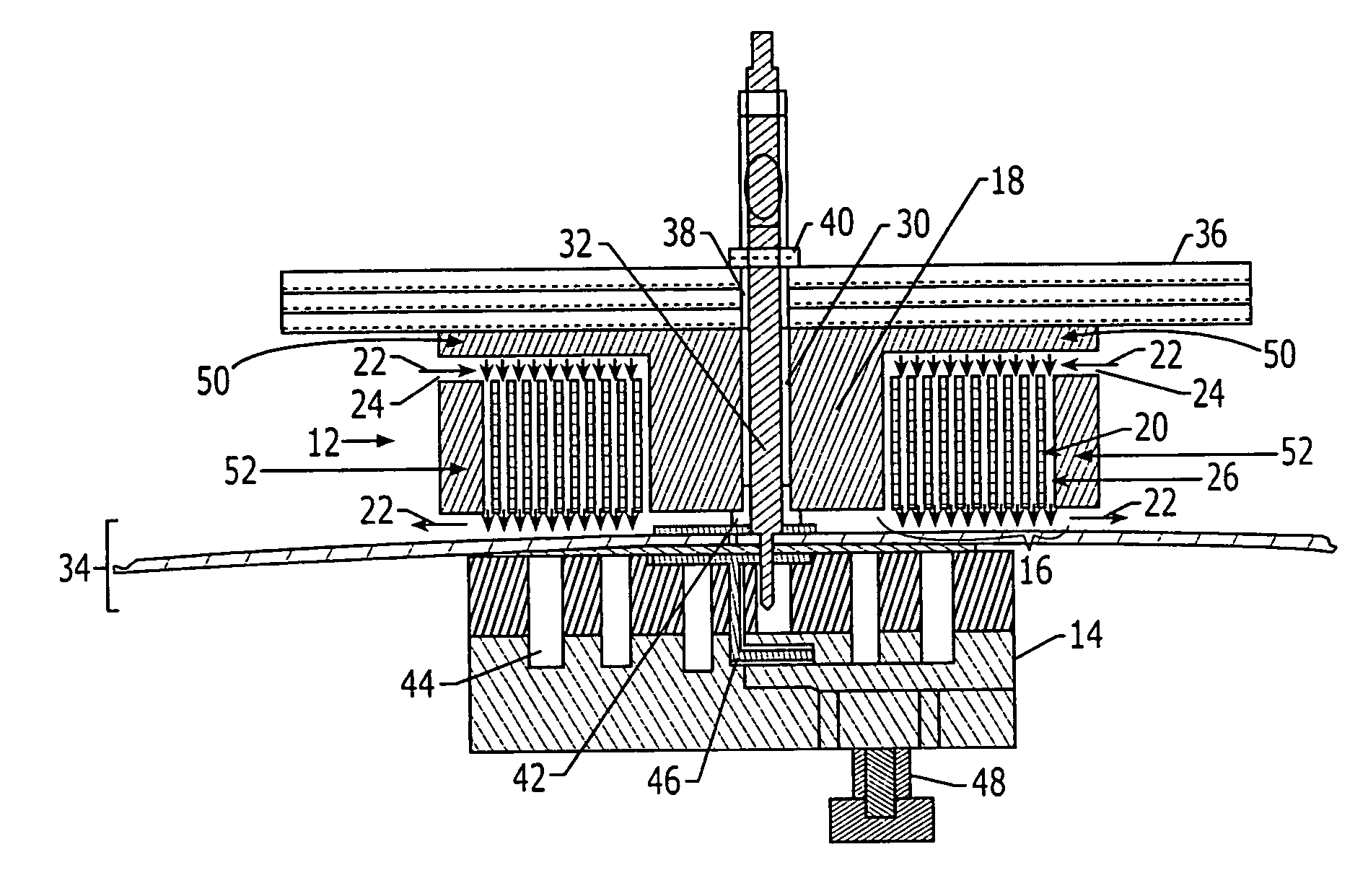
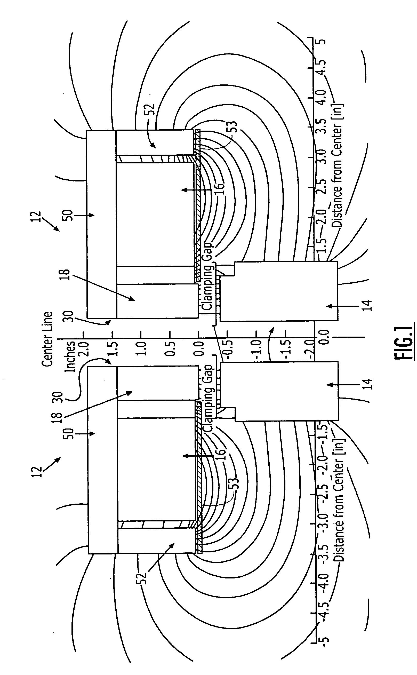
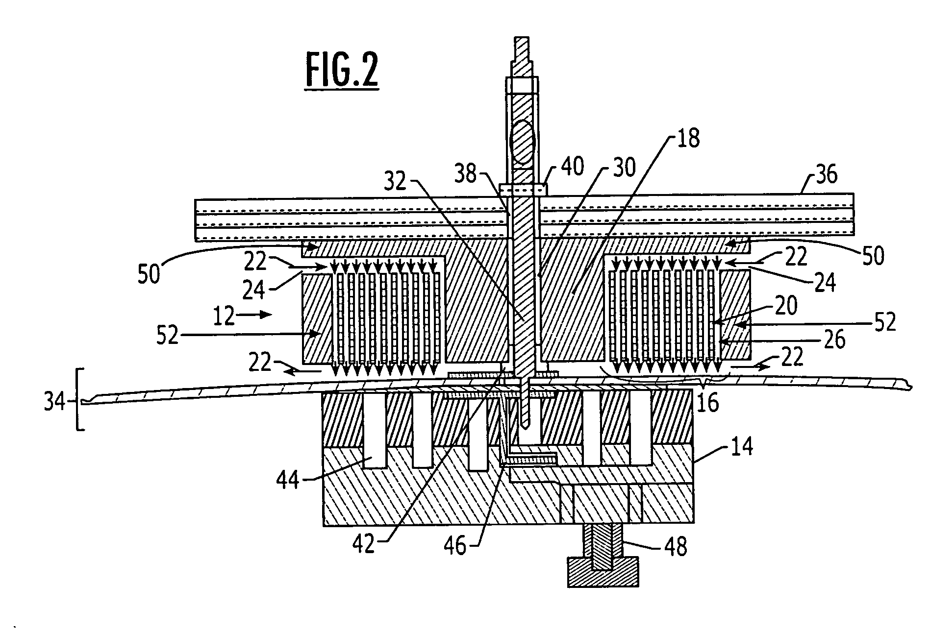
[0025] The electromagnetic clamp and method for clamping a structure of the present invention provide techniques for securely clamping structures, such as multiple layer structures, to prevent the layers of the structure from separating during an operation, while other aspects of the present invention provide a method for fabricating an electromagnet capable of creating the force necessary to securely clamp the structure. Due to the configuration of the core and coil of the electromagnet, it is capable of coo...


PUM

PropertyMeasurementUnit
thickaaaaaaaaaa
electric currentaaaaaaaaaa
internal magnetic fieldaaaaaaaaaa

Abstract

A method of of fabricating an electromagnet is provided in which a core having a flux return backplate on one end and a cover plate on the other end of the core is provided. For example, the flux return backplate may be fixed to one end of the core and the cover plate may be fixed to the other end of the core. A plurality of layers of wire may then be wound about the core between the flux return backplate and the cover plate, prior to fixing a flux return ring to the cover plate to at least partially enclose the wire.

Description

CROSS-REFERENCE TO RELATED APPLICATION [0001] The present application claims priority to and is a divisional of U.S. patent application Ser. No. 10 / 424,462 filed Apr. 28, 2003, the contents of which are incorporated herein in their entirety.BACKGROUND OF THE INVENTION [0002] The present invention relates to utilizing an electromagnetic assembly to securely clamp a structure, such as a multiple layer structure, and in particular to securely clamp the structure at a location where an operation is to be performed on the structure, while not obstructing the location where the operation is to be performed. [0003] In many industries, operations must be performed on structures, such as multiple layer structures, and problems arise if the multiple layers of the structure cannot be securely held together during the operation. For example multiple layer structures, particularly those structures that are subject to significant dynamic forces and / or pressure over their lifetime, such as aircraf...

Claims


Application Information

Patent Timeline
Patent Type & Authority Applications(United States)
IPC IPC(8): H01F7/20H01F7/06H01F7/16
CPCB25B11/002H01F7/20H01F2007/208Y10T29/4902Y10T29/49071Y10T29/49105Y10T29/49073
Inventor DAY, ARTHUR C.STANLEY, BRUCE DAVID
Owner THE BOEING CO
Why Eureka
Try Eureka