
Propulsion and stabilization struts for mower cutting deck

a technology of propulsion and stabilization struts and mower cutting boards, which is applied in the direction of mowers, agricultural tools and machines, etc., can solve the problems of excessive swaying or moving of the mower cutting boards, the lateral stabilization structure is prone to wear, and the structure wears and loosens up

Active Publication Date: 2009-07-23
EXMARK MFG
View PDF21 Cites 1 Cited by
  • Summary
  • Abstract
  • Description
  • Claims
  • Application Information

AI Technical Summary

Benefits of technology

[0011]One aspect of this invention relates to an improved mower of the type having a mower frame. A rotary cutting deck is carried by the frame. A height of cut system is provided for vertically moving the deck upwardly and downwardly relative to the frame to adjust the height of cut of the grass. In addition to the height of cut system, various struts propel and laterally stabilize the deck on the frame. The struts comprise a pair of laterally spaced, longitudinal struts pivotally connecting the frame to a rear of the deck for propelling the deck in forward and reverse directions as the frame moves in forward and reverse directions. At least one lateral strut pivotally connects the rear of the deck and the frame for providing lateral stabilization to the deck.
[0012]Another aspect of this invention relates to an improved mower of the type having a mower frame. A rotary cutting deck is carried by the frame. A plurality of struts extends between the deck and the frame. The improvement relates to the struts and comprises at least one generally longitudinally extending strut having opposite first and second ends, wherein a first end of each longitudinal strut is pivotally connected to the frame by a first pivot connection and a second end of each longitudinal strut is pivotally connected to the deck by a second pivot connection, and wherein the first and second pivot connections of each longitudinal strut are longitudinally spaced apart relative to a forward direction of motion of the frame such that each longitudinal strut propels the deck in forward and reverse directions from forward and reverse movement of the frame. The struts also comprise at least one generally laterally extending strut having opposite first and second ends. A first end of each lateral strut is pivotally connected to the frame by a first pivot connection and a second end of each lateral strut is pivotally connected to the deck by a second pivot connection. The first and second pivotal connections of each lateral strut are laterally spaced apart relative to the frame to laterally stabilize the deck on the frame. An elastomeric member is provided in at least one of the pivot connections of each strut.
[0013]Yet another aspect of this invention relates to an improved mower of the type having a mower frame. A rotary cutting deck is carried by the frame. A plurality of struts extends between the deck and the frame. The improvement relates to the struts and comprises at least three struts extending between the deck and the frame. At least one strut extends sufficiently longitudinally between the deck and the frame to propel the deck in forward and reverse directions as the frame moves in forward and reverse directions. At least one strut extends sufficiently laterally between the deck and the frame to stabilize the deck against lateral motion relative to the frame. At least one end of each strut includes a pivot connection permitting movement of the strut along three axes at the one end of the strut.

Problems solved by technology

However, this lateral stabilization structure is prone to wear due to the side loads involved.
Over time, this structure wears and loosens up and begins to permit the deck to excessively sway or move from side-to-side.
The structure can be rebuilt or repaired, but this is a disadvantage.
It is also a disadvantage to simply continue to use the cutting deck with too much side-to-side motion as the quality of cut can be adversely affected.
Another disadvantage of prior art struts is the use of solid pivot pins to connect opposite ends of the struts to the deck and the frame.
In addition, the use of solid pins to connect the struts is relatively noisy as the struts pivot up and down on the pins during operation of the mower and as the pins move slightly in their supports as the deck shifts laterally during maneuvering.
This noise can also be annoying to the operator or bystanders.
In addition, known strut designs are relatively difficult to assemble and require close tolerances.
However, it may be the case that after one strut is assembled in its forked mount, the placement of the front end of the other strut might be off when it comes to dropping it down between the arms of the other forked deck mount.
This requires the parts to be moved or replaced in order to allow assembly to be completed, which is obviously a disadvantage.

Method used


Image

  • Propulsion and stabilization struts for mower cutting deck
  • Propulsion and stabilization struts for mower cutting deck
  • Propulsion and stabilization struts for mower cutting deck

Examples


Embodiment Construction

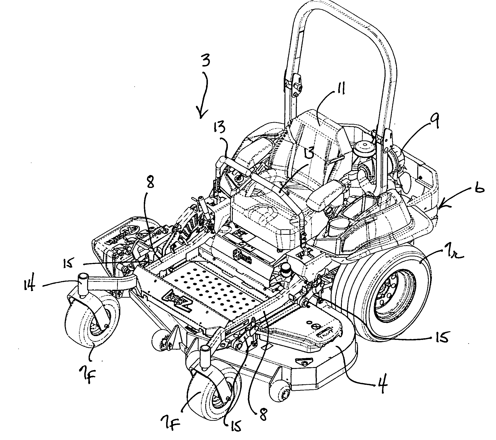
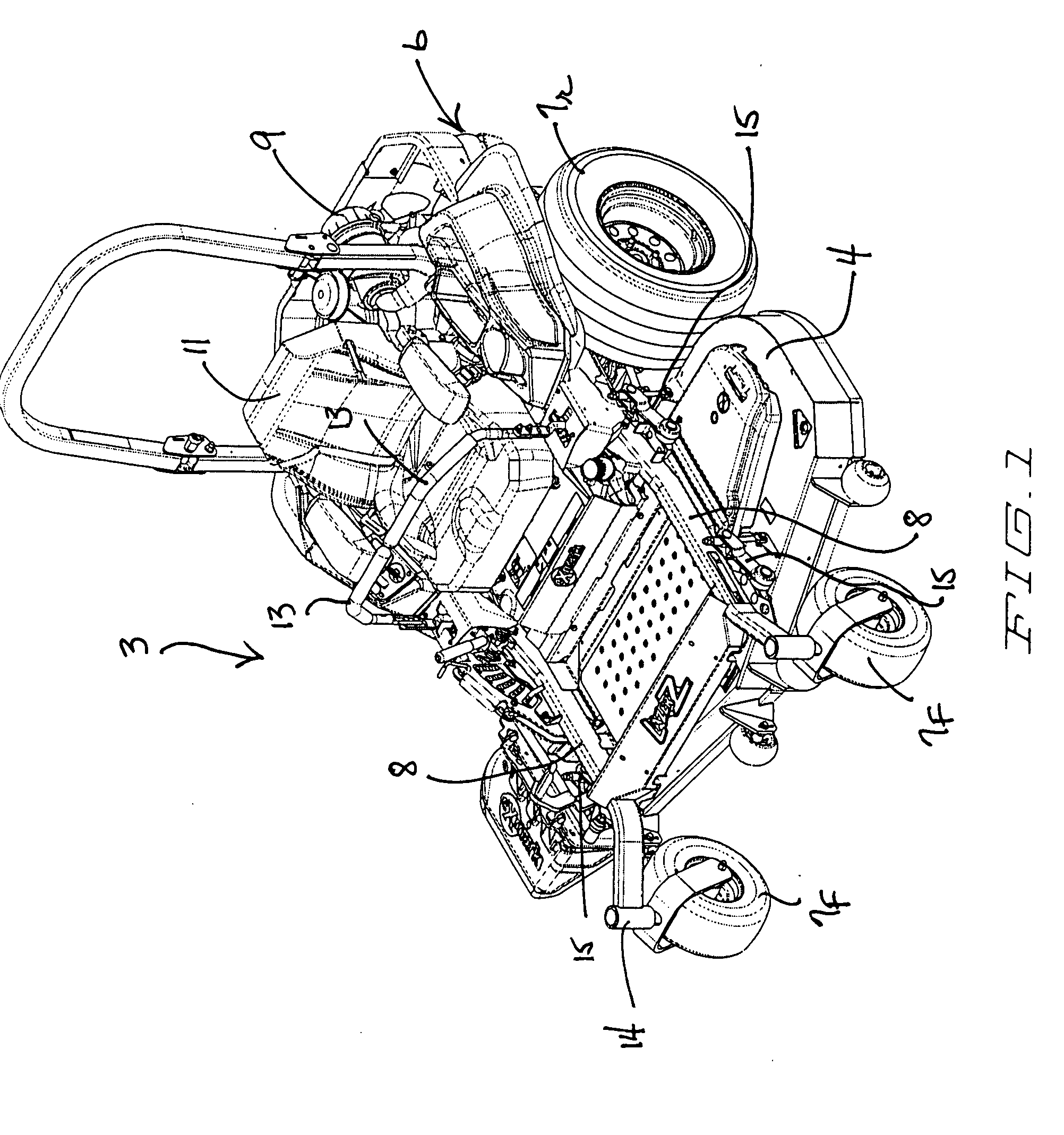
[0023]Referring first to FIG. 1, a mower 3 has a frame 6 that supports a rotary cutting deck 4 adjacent the front thereof. Frame 6 is supported for rolling over the ground by a pair of rear drive wheels 7r, only one of which is shown in FIG. 1, and by a pair of front caster wheels 7f. A power source, such as in internal combustion engine 9, is carried at the rear of frame 6. An operator's seat 11 is placed forward of engine 9 and generally between rear drive wheels 7r for carrying a seated operator. Two control levers 13 are used by the operator to control the steering and propulsion provided by rear drive wheels 7r in a manner well known for zero radius turn (ZRT) mowers. Other operational controls are provided for starting and stopping the operation of deck 4. Mower 3 as illustrated herein is similar to, but is not limited to, the Lazer Z mowers manufactured and sold by Exmark Mfg. Co., Inc., the assignee of this invention.

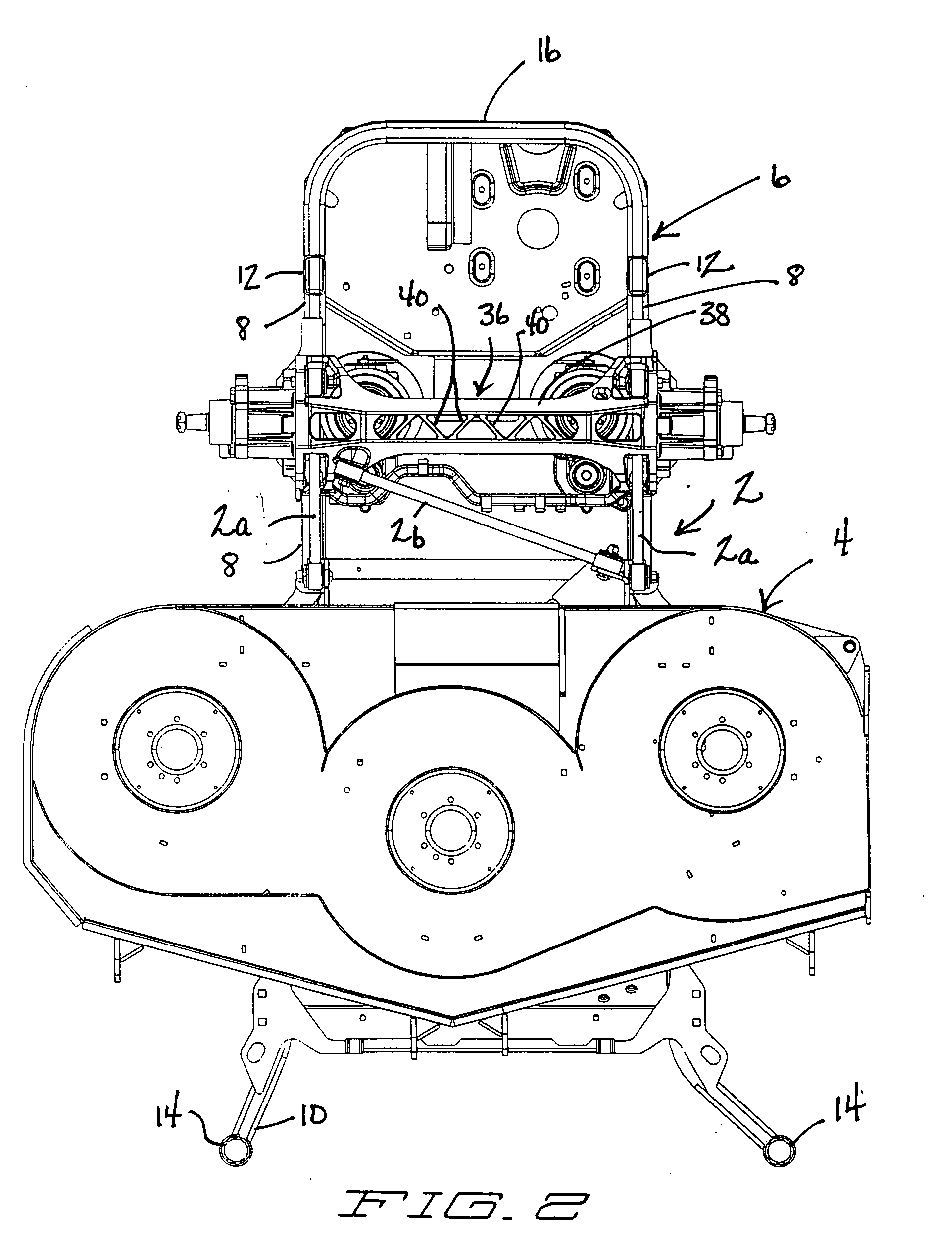
[0024]Referring now to FIG. 2, one embodiment of a set of ...


PUM


Abstract

A mower has a frame that supports a rotary cutting deck. A height of cut system is provided for adjusting the height of cut of the deck. In addition, two longitudinal struts and a lateral strut connect between the frame and the rear of the deck. The longitudinal struts propel the deck in forward and reverse directions while the lateral strut provides lateral stabilization to the deck to prevent excessive side-to-side motion of the deck. Each of the struts is a simple elongated rod or bar having a hub at either end that contains a rubber bushing allowing three-axis motion. Each strut is pivotally connected at each hub to corresponding portions of the frame or the deck.

Description

TECHNICAL FIELD[0001]This invention relates to a rotary cutting deck mounted to and carried by a mower. More particularly, this invention relates to a plurality of struts extending between the mower frame and the cutting deck to propel the cutting deck and to laterally stabilize the cutting deck against undue side-to-side movement.BACKGROUND OF THE INVENTION[0002]Riding mowers having a zero radius turn (ZRT) capability are well known in the mowing art. Such mowers have a frame that carries a power source, such as an internal combustion engine, for propelling the frame over the ground and for providing power for mowing. Two powered rear drive wheels are carried on the frame with the front of the frame having a pair of unpowered front wheels, the wheels collectively supporting the frame for rolling over the ground. Often, the unpowered front wheels are caster wheels.[0003]The rear drive wheels in a ZRT mower are individually powered by separate hydraulic drive motors that receive pres...

Claims


Application Information

Patent Timeline
Patent Type & Authority Applications(United States)
IPC IPC(8): A01D34/00
CPCA01D34/74
Inventor FINKNER, STEVEN C.WOLFF, KERMIT A.
Owner EXMARK MFG
Learn More