Retractable duck decoy weight

a duck and weight technology, applied in the field of duck decoy weight and weight retracting, can solve the problems of affecting the ability of the hunter to maintain a desired, decoys to undesirably interact with each other, and affecting the anchoring ability of the weight,

Pending Publication Date: 2020-10-15
CLARK JACOB
View PDF19 Cites 2 Cited by
  • Summary
  • Abstract
  • Description
  • Claims
  • Application Information

AI Technical Summary

Benefits of technology

[0008]In concordance and agreement with the present invention, a new and improved wei

Problems solved by technology

However, the body of water having the decoys may be subjected to wind above the surface of the body of water or a water current present within the body of water that tends to cause the decoys to float away from the desired location, which in turn negatively affects the ability of the hunter to maintain a desired grouping of the decoys adjacent the desired hunting area.
If the line is too long, the decoys may tend to float within a greater range than is desired or may cause the decoys to undesirably interact with each other.
In contrast, if the line is too short, the anchoring capabilities of the weight may be compromised and the decoys may float to undesired positions.
The use of a simple line that is attached to the decoy according presents several issues in attempting to reach the desired length of the line with respect to the given depth of the water chosen for the hunting position.
Additionally, when retracting the line the hunter must utilize the time-consuming method of hand-retracting the line when it is desired to leave the given location at the conclusion of the hunting session or when it is desired to reposition the decoys.
It is not uncommon for such waterfowl hunters to utilize as many as 60 such decoys at a given location, so this process becomes excessively cumbersome as a result of the large number of retractions that must be performed each time the decoys are removed from the given location.
However, such mechanisms usually include various shortcoming

Method used


Image

  • Retractable duck decoy weight
  • Retractable duck decoy weight
  • Retractable duck decoy weight

Examples


Embodiment Construction

[0034]The following detailed description and appended drawings describe and illustrate various exemplary embodiments of the invention. The description and drawings serve to enable one skilled in the art to make, and use the invention, and are not intended to limit the scope of the invention in any manner. With respect to the methods disclosed, the steps presented are exemplary in nature, and thus, the order of the steps is not necessary or critical.

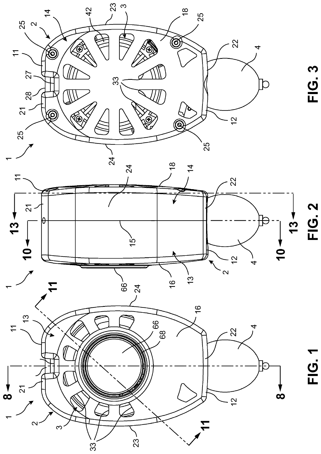
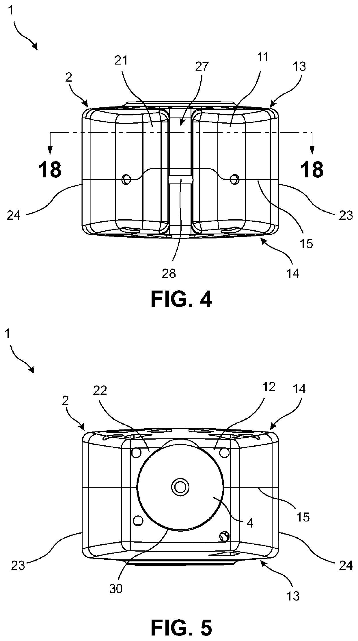
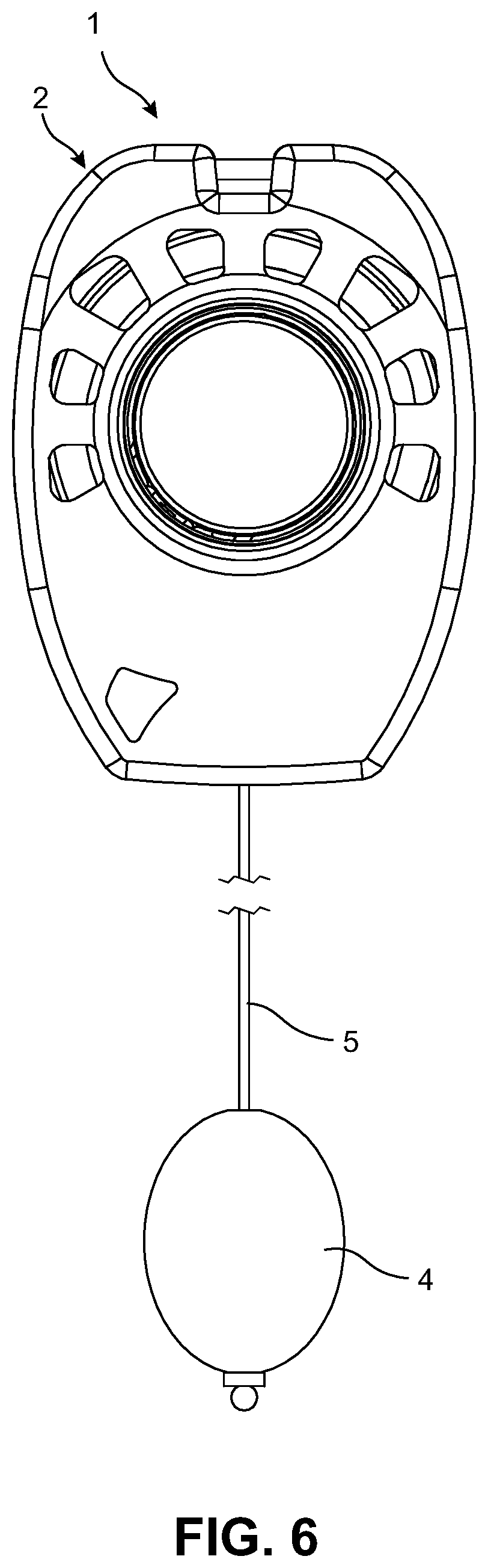
[0035]FIGS. 1-22 illustrate a weight retraction device 1 for use with waterfowl decoys according to an embodiment of the present invention, wherein the weight retraction device 1 is referred to as the device 1 hereinafter for brevity. As shown in FIG. 7, the device 1 is configured for removable coupling to an associated waterfowl decoy 200. The waterfowl decoy 200 may be representative of any type of decoy typically configured to float on the surface of a body of water, such as the duck-shaped decoy illustrated herein. However, one skille...


PUM


Abstract

A weight retraction device for use with a waterfowl decoy includes a housing having a spool rotatably coupled thereto. A weight is attached to a line that is wound around the spool. Rotation of the spool in a first rotational direction causing an unwinding of the line from the spool to cause the weight to extend away from the housing while rotation of the spool in a second rotational direction causing a rewinding of the line back onto the spool to cause the weight to retract back towards the housing. A power spring is configured to urge the spool to rotate in the second rotational direction. A lock release mechanism is configured to normally be in a locked configuration for preventing an undesired rotation of the spool in the second rotational direction. A manual actuation of the lock release mechanism releases the locked configuration of the lock release mechanism.

Description

FIELD[0001]This patent application claims priority to U.S. Provisional Patent Application Ser. No. 62 / 832,327, filed on Apr. 11, 2019, the entire disclosure of which is hereby incorporated herein by reference.FIELD OF THE INVENTION[0002]The present invention relates generally to a device for retracting a weight to be attached to a floating waterfowl decoy, and more specifically, to a device configured to place a line attached to the weight in a locked position when the line has been extended to a desired length from the device and to then retract the weight from the locked position in response to an operator manually actuating a lock release mechanism.BACKGROUND OF THE INVENTION[0003]The use of decoys for hunting waterfowl is widely utilized by waterfowl hunters as these decoys aid in attracting the waterfowl to the area being hunted. Such waterfowl decoys are typically deployed to float on top of a body of water with the intention of the decoys remaining in place during the hunting...

Claims


Application Information

Patent Timeline
IPC IPC(8): A01M31/06B65H75/48
CPCB65H75/486A01M31/06B65H75/4431B65H2701/35
Inventor CLARK, JACOB
Owner CLARK JACOB
Why Eureka
Try Eureka