Golf Putter Head for Ensuring Pure Roll

a golf putter and pure roll technology, applied in the field of golf putters, can solve the problems of reducing the accuracy of the putter, and preventing the initiation of the more accurate, controlled pure roll phase, and achieving the effect of reducing club drag

Pending Publication Date: 2020-11-12
KORN DAVID R
View PDF15 Cites 0 Cited by
  • Summary
  • Abstract
  • Description
  • Claims
  • Application Information

AI Technical Summary

Benefits of technology

[0020]In an embodiment, the sole pillar comprises a set of guides on its bottom side to reduce club drag.
[0021]In an embodiment, the sole pillar is removable and fixedly attached to the putter head with screws or other fasteners. In another embodiment, the putter head has a recessed portion on the top of the strike face such that the width of the recess is equal to a golf ball diameter so that the golfer can visually align the golf ball to the putter face by aligning, visually, the recessed edges to the golf ball outer diameter.
[0022]In another embodiment, the base of the sole pillar has a flat area between that can rest on the green. The flat being greater than 1 inch in length measured along the axis defined by a line between the sole to the heel of the club. This flat will also have a width that is equal to the width of the sole pillar less any curvature to eliminate sharp edges that might contact the green during a swing and catch on the grass, which would modify the energy imparted to the golf ball.
[0023]In yet another embodiment, the top of the putter head has a recessed cut that creates two different planar areas. The first planar area contacts the top of the strike face and is created by the said recess to aid aligning the club to the golf ball via the edges of the recess being the same width as the golf ball. The second planar area is a second recess behind the strike face and is at a different and lower elevation compared to the first planar area. One line is placed on the first planar area at the center of the recess to indicate the alignment position for the center of the ball. This helps the golfer align the putter face in a horizontal plane, parallel to the golf green, and in the direction forward and backward of the golf ball. In other words, this adjusts the location where the ball will contact the putter strike face edge. A second line is placed on the second planar area. The vertical separation of these two lines provide the golfer with an independent method of alignment of his or her eyes relative to the putter and the golf ball.
[0024]In yet another embodiment, the flat on the bottom of the sole pillar, the two alignment marks on the first and second planar surfaces, and the first planar surface recess are all included. Together these allow the golfer to create a more repeatable stance compared to any other putter. First, the golfer can rock the putter forward and backward while sitting on the green. The flat on the pillar enables the golfer to “feel” when the putter is flat to the green. Second, the golfer aligns the putter recessed first planar surface and the alignment mark on that first planar surface to ensure that the golf ball will strike the putter strike face in the proper position. Third, the second alignment mark on the second planar surface enables the golfer to move his or her head forward or backward, while the putter is flat to the green, until his or her head position causes the two separated alignment marks to become visually aligned.

Problems solved by technology

Backspin is undesirable because it reduces putt accuracy, and delays the initiation of the more accurate, controlled pure roll phase.
These counterproductive results equate to false roll, random energy deposition, and inconsistent putting scores.

Method used


Image

  • Golf Putter Head for Ensuring Pure Roll
  • Golf Putter Head for Ensuring Pure Roll
  • Golf Putter Head for Ensuring Pure Roll

Examples


Embodiment Construction

[0050]The following description describes solely a preferred embodiment of the present invention, and is not meant to limit the invention to that particular embodiment. The invention is limited solely by the claims.

Nomenclature, Terminology, and Engineering Model Conventions

[0051]The reference numbers used in the present disclosure are listed in Table 2.

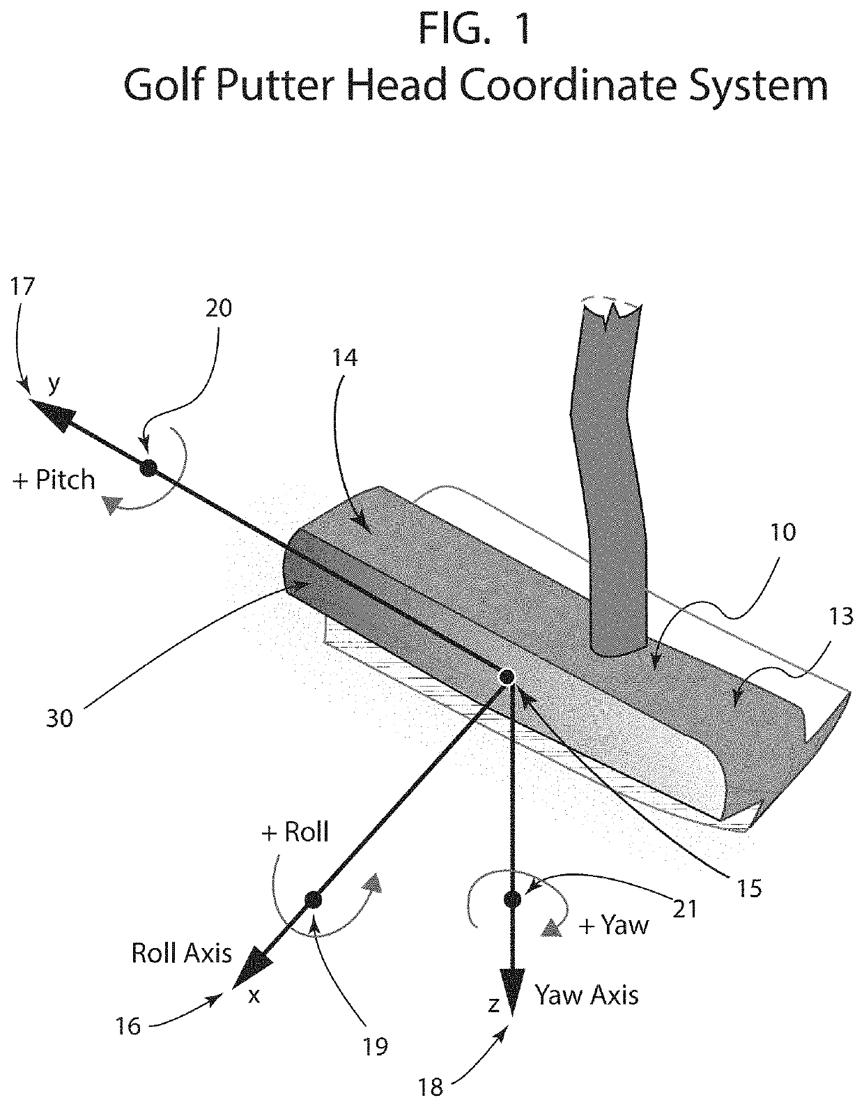
[0052]FIG. 1 depicts the putter head 10 parameters which are defined using 6-degree-of-freedom 15 modeling conventions. The translational parameters are in a standard x 16, y 17, and z 18 coordinate system with corresponding rotations of roll 19, pitch 20, and yaw 21. The right hand rule is used to determine positive angular rotations.

[0053]Roll 19, denoted by .phi., is rotation about the x-axis 16. A positive roll angle corresponds to a heel-up / toe-down putter head and a negative yaw angle is a heel-down / toe-up rotation. The heel is referred to as 13 and the toe is referred to as 14.

[0054]Pitch 20, denoted by .theta., is rotation ab...


PUM


Abstract

A new golf putter head is disclosed, comprising an upper portion and a sole pillar, wherein the upper portion comprises a strike face and the bottom edge of the strike face is used to strike the golf ball on the golf ball equator, and the sole pillar does not contact the ball at any point during the ball contact with the putter during the swing, the putter improving the putt accuracy by reducing golf ball slippage on the green and the variability of the energy deposited into the golf ball on a putt.

Description

RELATED U.S. PATENT DOCUMENTS[0001]The present application is a continuation in part of application Ser. No. 15 / 155,081, filed May 16, 2016, which takes priority from App. No. 62 / 162,723, filed May 16, 2015, which are both herein incorporated by reference.DESCRIPTIONCross-Reference to Related Applications[0002]The present invention is a continuation in part of application Ser. No. 15 / 155,081, filed May 16, 2016, which takes priority from Provisional App. No. 62 / 162,723, filed May 16, 2015, which is incorporated herein by reference.BACKGROUNDField of the Invention[0003]The present invention relates generally to golf putters, and more particularly to golf putter heads that ensure that the ball rolls with minimal slippage. The golf putter head is designed to strike the ball on the bottom edge of the strike face and doing so eliminates the typical ball backspin and ball energy deposition variability, thereby improving putt accuracy.Background of the Invention[0004]This invention relates...

Claims


Application Information

Patent Timeline
Patent Type & Authority Applications(United States)
IPC IPC(8): A63B53/06A63B53/04
CPCA63B53/0433A63B53/065A63B53/0441A63B53/0408A63B2225/093A63B2209/08A63B60/006A63B60/02A63B60/42A63B53/0487A63B53/021
Inventor KORN, DAVID R
Owner KORN DAVID R
Why Eureka
Try Eureka