S-lock flashing member forming apparatus

a technology of flashing member and forming apparatus, which is applied in the direction of metal-working apparatus, etc., can solve the problems of limited control over the precise, high labor intensity and high cost of the process, and achieve the effect of simple pressing operation

Active Publication Date: 2016-12-13
MARSHALL JOSEPH T
View PDF4 Cites 1 Cited by
  • Summary
  • Abstract
  • Description
  • Claims
  • Application Information

AI Technical Summary

Benefits of technology

[0015]Alternatively, additional functionality may be provided to the die members of the apparatus according to the present invention to allow the die members to complete the flattening of the Z-shaped profile of partially formed bends into the finished S-lock end joint.
[0020]By providing three separate die members supported for various movements relative to a work surface as described herein, the path of the sheet metal used to form the S-lock end joint in the flashing member can be precisely controlled with minimal slippage relative to the die members. Accordingly, the process can be readily automated in the operation of the forming apparatus while producing a very accurate finished product. Furthermore, minimal slippage of the sheet metal relative to the die members avoids any unnecessary scratching of the finished product.

Problems solved by technology

As presently practiced in the industry, slip locks can be formed using conventional sheet metal bending equipment but the process involves many steps and is therefore very labour intensive and expensive.
By using only two dies, which are forced together, the sheet metal involves some relative sliding against the surfaces of the die during the forming process which produces scratches in the finished product and provides limited control over the precise path which the sheet metal is bent to produce the S-lock joint.

Method used


Image

  • S-lock flashing member forming apparatus
  • S-lock flashing member forming apparatus
  • S-lock flashing member forming apparatus

Examples


Embodiment Construction

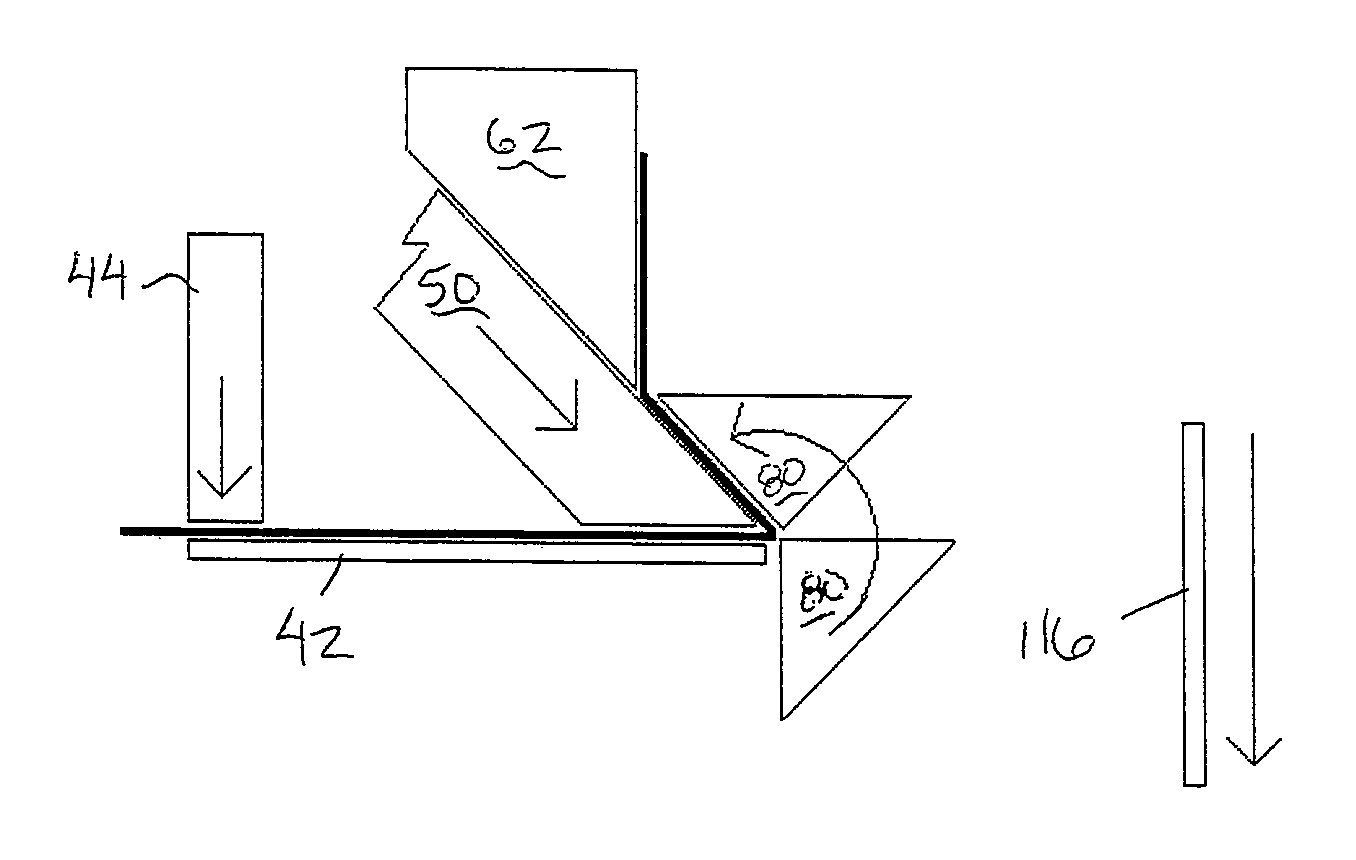
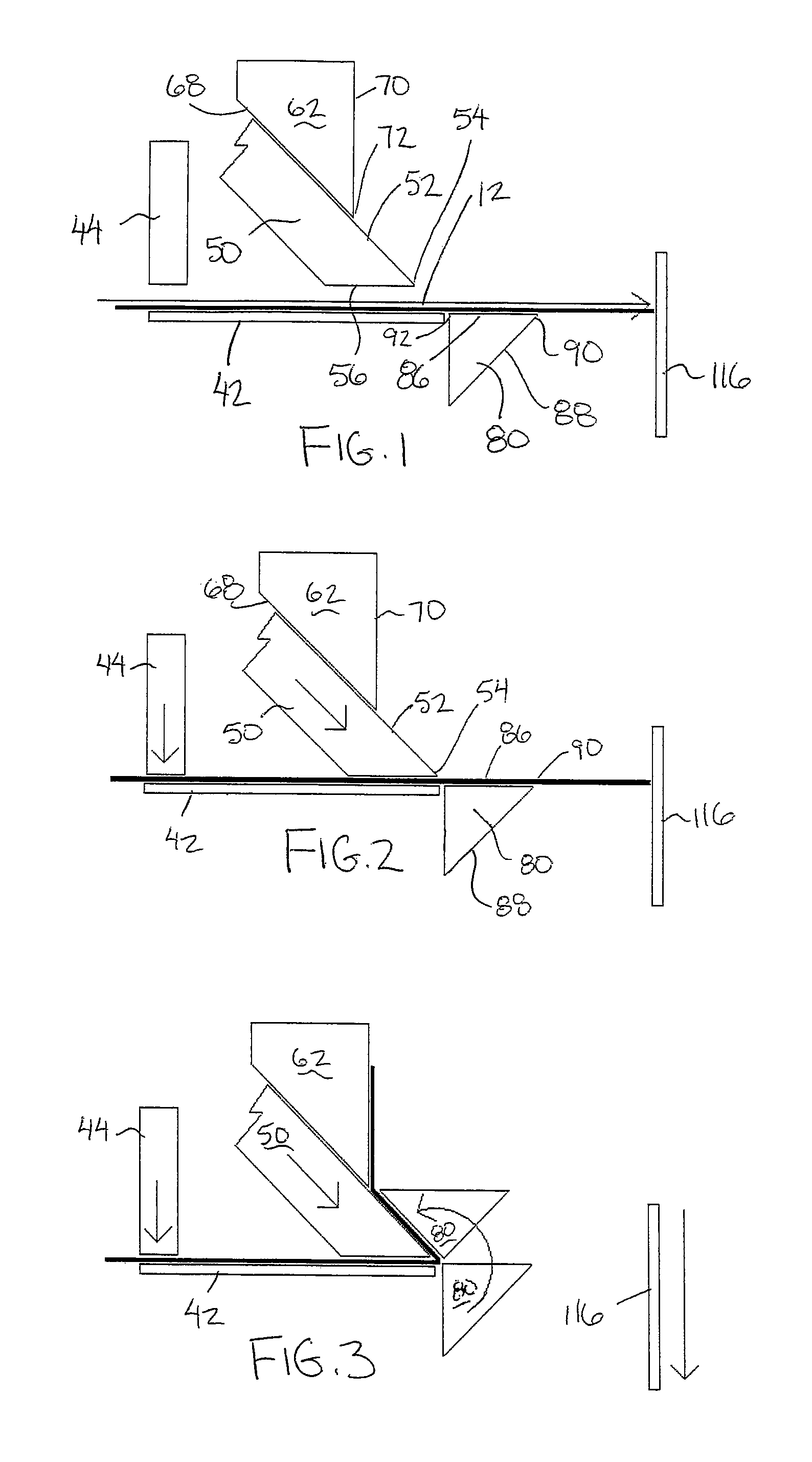
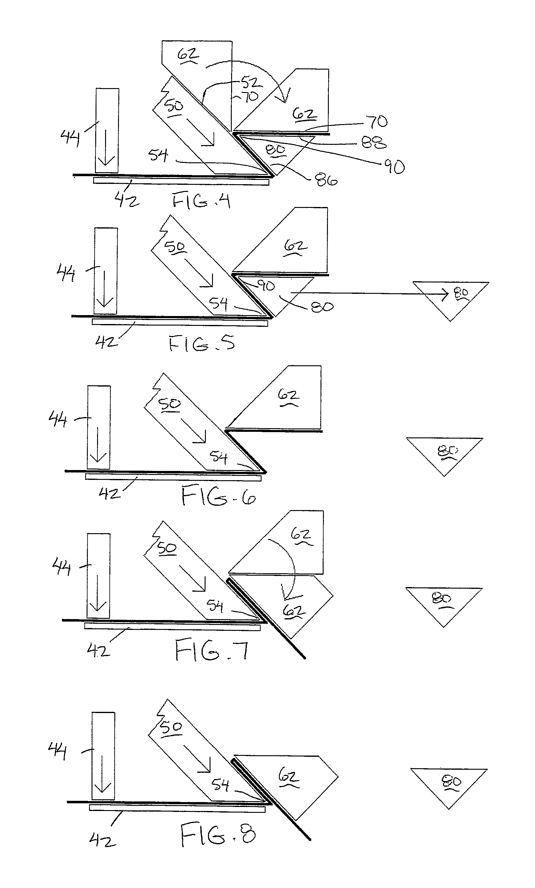
[0040]Referring to the accompanying figures, there is illustrated a forming apparatus generally indicated by reference numeral 10. The forming apparatus is particularly suited for forming an S lock end joint in a flashing member formed of sheet metal.

[0041]More particularly, the forming apparatus bends the flashing member 12 such that the resulting flashing member includes a generally planar main portion 14 terminating at an outer end forming a first bend 16. The first bend 16 is an approximately 180 degree fold between the longitudinal direction of the main portion 14 and a generally planar intermediate portion 18 which is folded back alongside the main portion 14 from the first bend 16 at one edge to a second bend 20 at the opposing edge of the intermediate portion. At the second bend 20, the sheet metal is again folded through 180 degrees such that the remaining end portion of the flashing member defines a fastener portion 22 extending alongside the intermediate portion to extend...


PUM

PropertyMeasurementUnit
acute interior angleaaaaaaaaaa
angleaaaaaaaaaa
interior angleaaaaaaaaaa

Abstract

A forming apparatus includes a work surface and three die members movable relative to the work surface for bending a sheet metal flashing member to form an S-shaped end joint known as an S-lock or slip lock joint.

Description

[0001]This application claims foreign priority benefits from Canadian Patent Application 2,852,327 filed May 23, 2014.FIELD OF THE INVENTION[0002]The present invention relates to a forming apparatus for bending sheet metal, and more particularly the present invention relates to a forming apparatus for bending an S-shaped end joint on a flashing member, for example roof flashing members for use on a building exterior.BACKGROUND[0003]In the roofing industry it is common to use sheet metal flashing for sealing and finishing various roof edges. The flashing members typically comprise elongate metal sheets in varying lengths and widths which are interlocked with one another at respective ends by a slip lock or S-lock joint. The general profile of an S-lock joint is essentially a flattened S such that the sheet member forms a main portion of the flashing member, an intermediate portion folded back over top of the main portion, and a free end portion extending back across the intermediate ...

Claims


Application Information

Patent Timeline
Patent Type & Authority Patents(United States)
IPC IPC(8): B21D5/16B21D5/01B21D53/00
CPCB21D5/16B21D5/01B21D53/00
Inventor MARSHALL, JOSEPH T.
Owner MARSHALL JOSEPH T
Why Eureka
Try Eureka