Inductor magnetic-core structure

a technology of magnetic core and inductance, applied in the field of magnetic core, can solve the problems of inconvenient design, and achieve the effect of reducing circuit design and convenient manufactur

Inactive Publication Date: 2020-11-19
TAI TECH ADVANCED ELECTRONICS CO LTD
View PDF0 Cites 0 Cited by
  • Summary
  • Abstract
  • Description
  • Claims
  • Application Information

AI Technical Summary

Benefits of technology

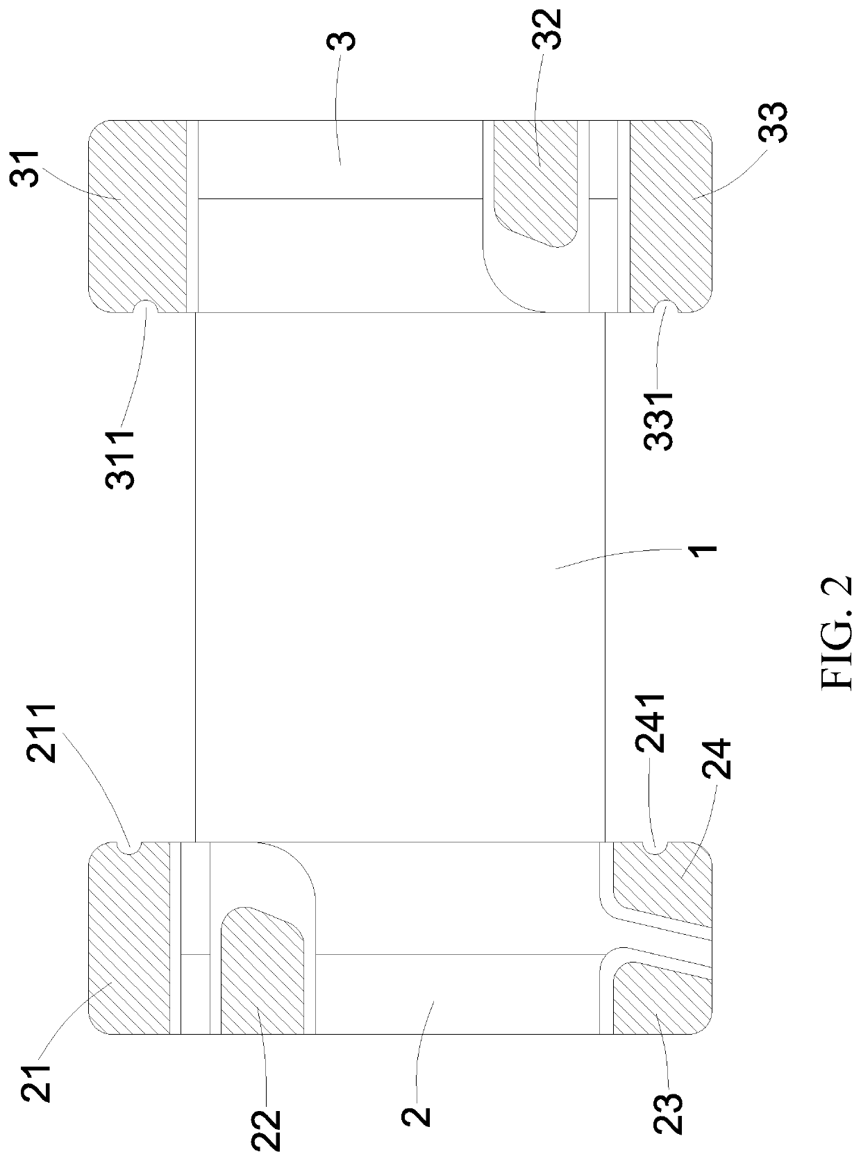
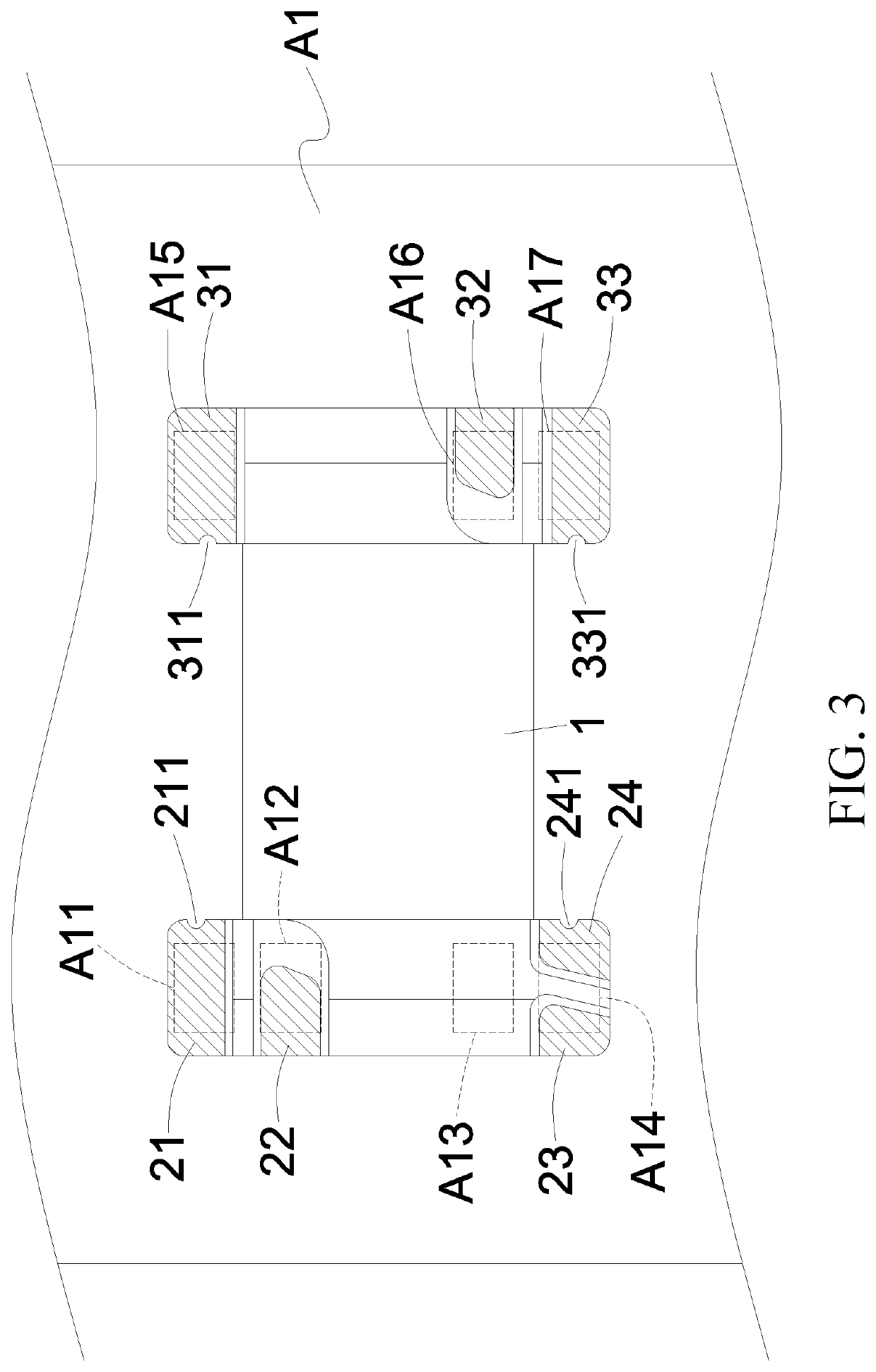
The present invention provides an inductor magnetic-core structure that includes multiple electrodes and grooves for supporting winding wires. With these features, the structure allows for easy manufacture and change of winding wires, as well as control of winding directions. This results in a more flexible and efficient product design.

Problems solved by technology

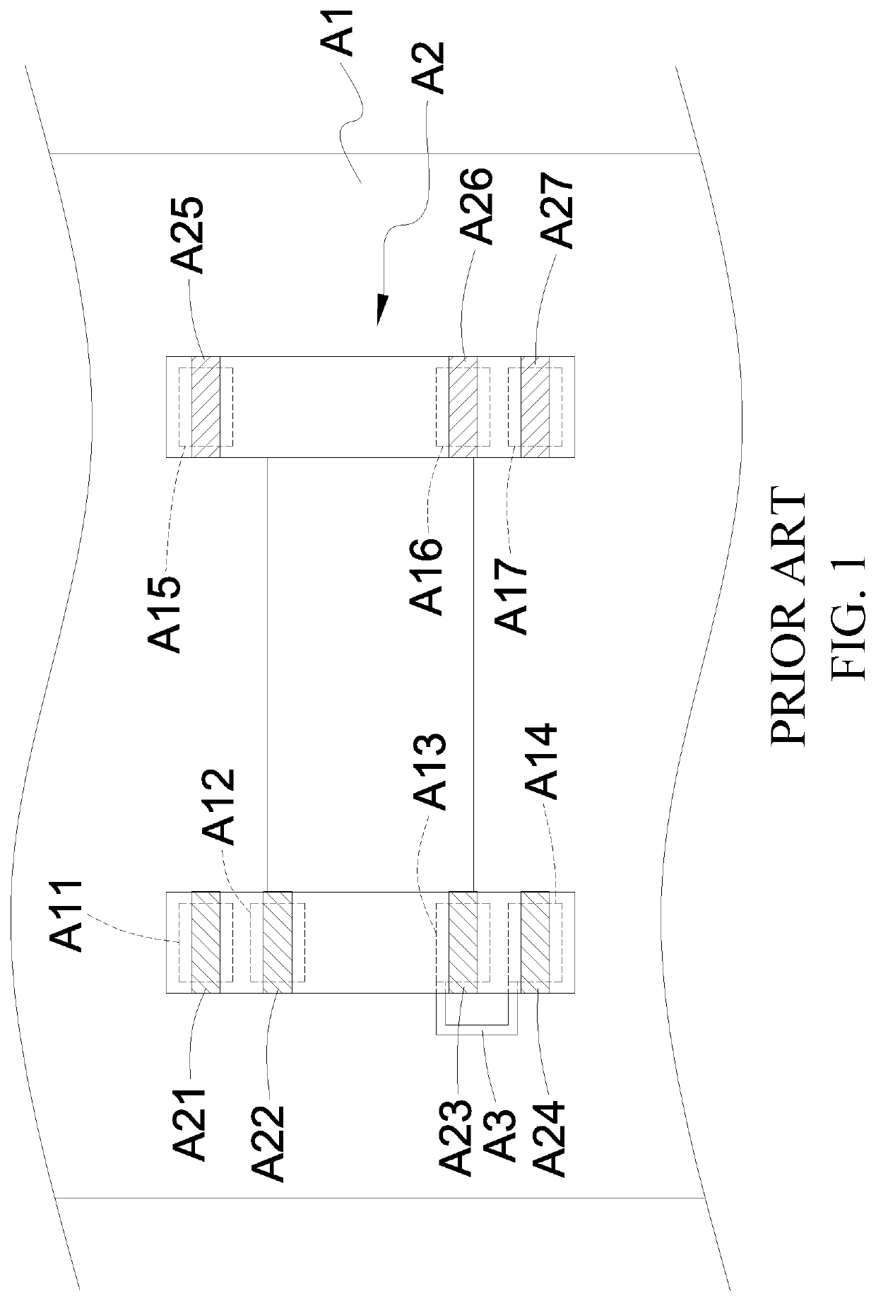
The conventional inductor magnetic-core A2 can be quickly bonded with the circuit board, but between the contact-point A13 and the fourth contact-point A14 needs to additionally add a short-circuit line A3 on the circuit board; and when adding a short-circuit line on the circuit board, it is often inconvenient for the design because of adding an additional process step and needing to consider the design of the layer plates of the circuit board.

Method used


Image

  • Inductor magnetic-core structure
  • Inductor magnetic-core structure
  • Inductor magnetic-core structure

Examples


Embodiment Construction

[0010]The following descriptions are exemplary embodiments only, and are not intended to limit the scope, applicability or configuration of the invention in any way. Rather, the following detailed description provides a convenient illustration for implementing exemplary embodiments of the invention. Various changes to the described embodiments may be made in the function and arrangement of the elements described without departing from the scope of the invention as set forth in the appended claims.

[0011]The foregoing and other aspects, features, and utilities of the present invention will be best understood from the following detailed description of the preferred embodiments when read in conjunction with the accompanying drawings.

[0012]Please refer to FIG. 2, the present invention provides an inductor magnetic-core structure, which comprises a magnetic-core main-body 1 set with a first flange 2 and a second flange 3 at both ends of the magnetic-core main-body 1; wherein a first elect...


PUM


Abstract

An inductor magnetic-core structure comprises a magnetic-core main-body set with a first flange and a second flange; wherein a first electrode, a second electrode, a third electrode, and a fourth electrode are set on the first flange; wherein a first groove is set on the first electrode, and a second groove is set on the fourth electrode; wherein a fifth electrode, a sixth electrode, and a seventh electrode are set on the second flange; wherein a third groove is set on the fifth electrode, and a fourth groove is set on the seventh electrode; Through the third electrode and the fourth electrode are laterally adjacent and are vertical arranged with respect to the first electrode and the second electrode, and the third electrode and the fourth electrode are set on the fourth contact-point; it does not need to design a short-circuit line on the circuit board additionally.

Description

(a) TECHNICAL FIELD OF THE INVENTION[0001]The present invention relates to a magnetic-core, and especially relates to an inductor magnetic-core structure.(b) DESCRIPTION OF THE PRIOR ART[0002]Please refer to FIG. 1, generally the inductor used for surface-mounting on the circuit board is mainly set with a conventional first electrode A21, a conventional second electrode A22, a conventional third electrode A23, a conventional fourth electrode A24, a conventional fifth electrode A25, a conventional sixth electrode A26, and a conventional seventh electrode A27 respectively at two ends of a conventional inductor magnetic-core A2; wherein the conventional electrodes A21, A22, A23, A24, A25, A26, and A27 can be correspondingly and oppositely bonded and connected with the first contact-point A11, the second contact-point A12, the third contact-point A13, the fourth contact-point A14, the fifth contact-point A15, the sixth contact-point A16, and the seventh contact-point A17 of the circuit ...

Claims


Application Information

Patent Timeline
IPC IPC(8): H01F27/24
CPCH01F27/2823H01F27/24H01F17/045H01F27/2828H01F27/29
Inventor YANG, HSIANG CHUNGSHEN, PAO LINHSIEH, MING YEN
Owner TAI TECH ADVANCED ELECTRONICS CO LTD
Why Eureka
Try Eureka