Sliding device with onboard moving-magnet linear motor

a linear motor and sliding device technology, applied in the direction of propulsion systems, electrical apparatus, dynamo-electric machines, etc., can solve the problems of reducing the propulsion thrust of the moving table, requiring many working steps, and deep recesses in the moving table, so as to achieve high propulsion, high production efficiency, and convenient manufacturing

Active Publication Date: 2005-11-24
NIPPON THOMPSON
View PDF7 Cites 16 Cited by
  • Summary
  • Abstract
  • Description
  • Claims
  • Application Information

AI Technical Summary

Benefits of technology

[0017] The sliding device of the present invention constructed as stated earlier is envisaged further developing the prior sliding device so as to allow a moving table traveling for reciprocation over longer stroke with higher in propulsion, traveling velocity and response ability, compared with the prior sliding device. The sliding device of the present invention is moreover convenient for manufacturing at high production efficiency the small sliding device, which meets the requirements for long traveling stroke, even with small or compact in construction.

Problems solved by technology

If that happens, the magnetic flux heading toward the armature windings might become less intense so that the propulsion to thrust the moving table would result in getting reduced remarkably.
Making the deep recess into the moving table, moreover, needs many working steps.
Making the bed into the H-shape sophisticated in construction would also take much effort in working processes.
Thus, the small sliding device with onboard linear motor first recited earlier is inconvenient for manufacturing at high production efficiency the small sliding device, which meets the requirements for high propulsion, high response and long traveling stroke.
In the prior sliding device constructed as stated earlier, nevertheless, there is no way to install in place the field magnets of even more poles, for example eight poles to cope with the challenge to higher propulsion, higher response, longer traveling stroke, and so on.
Cutting deep the recess into the bed would also take much effort in working processes.
This also makes the bed in construction more complicated to need much additional working steps.
Thus, it remains a major challenge to further develop the sliding devices disclosed in the commonly assigned Japanese Patent application as recited earlier so as to allow the moving table operating over longer traveling stroke, enhancing the propulsion, traveling velocity, high response, and so on, even with small or compact in construction and better in production efficiency.

Method used


Image

  • Sliding device with onboard moving-magnet linear motor
  • Sliding device with onboard moving-magnet linear motor
  • Sliding device with onboard moving-magnet linear motor

Examples


Embodiment Construction

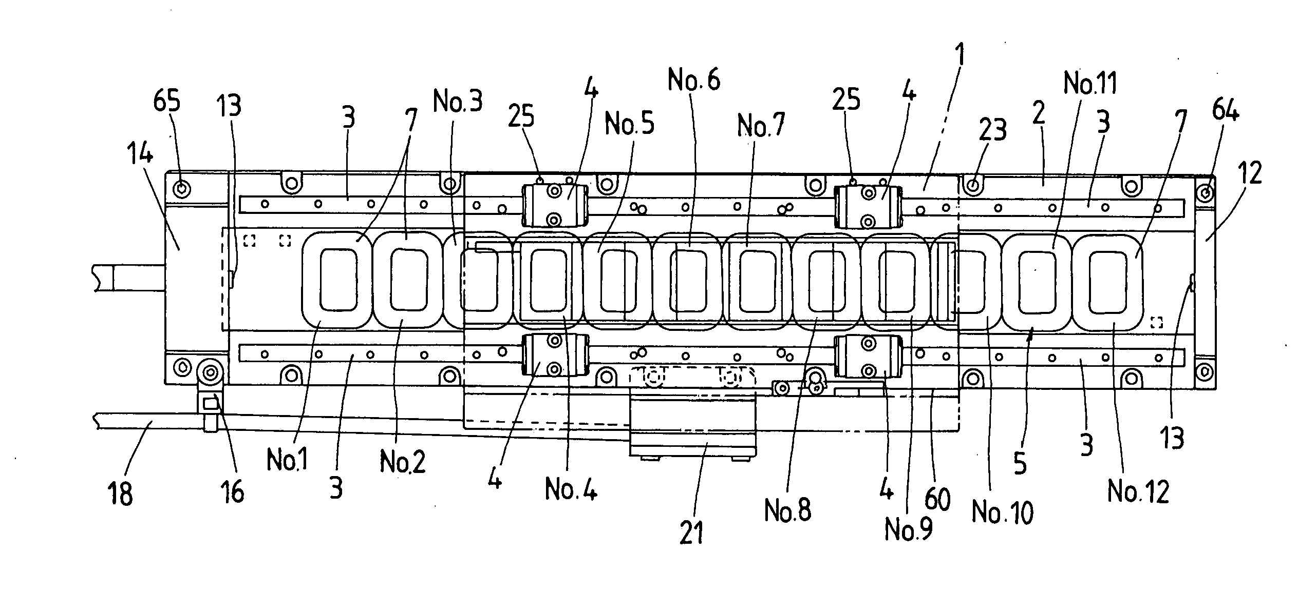
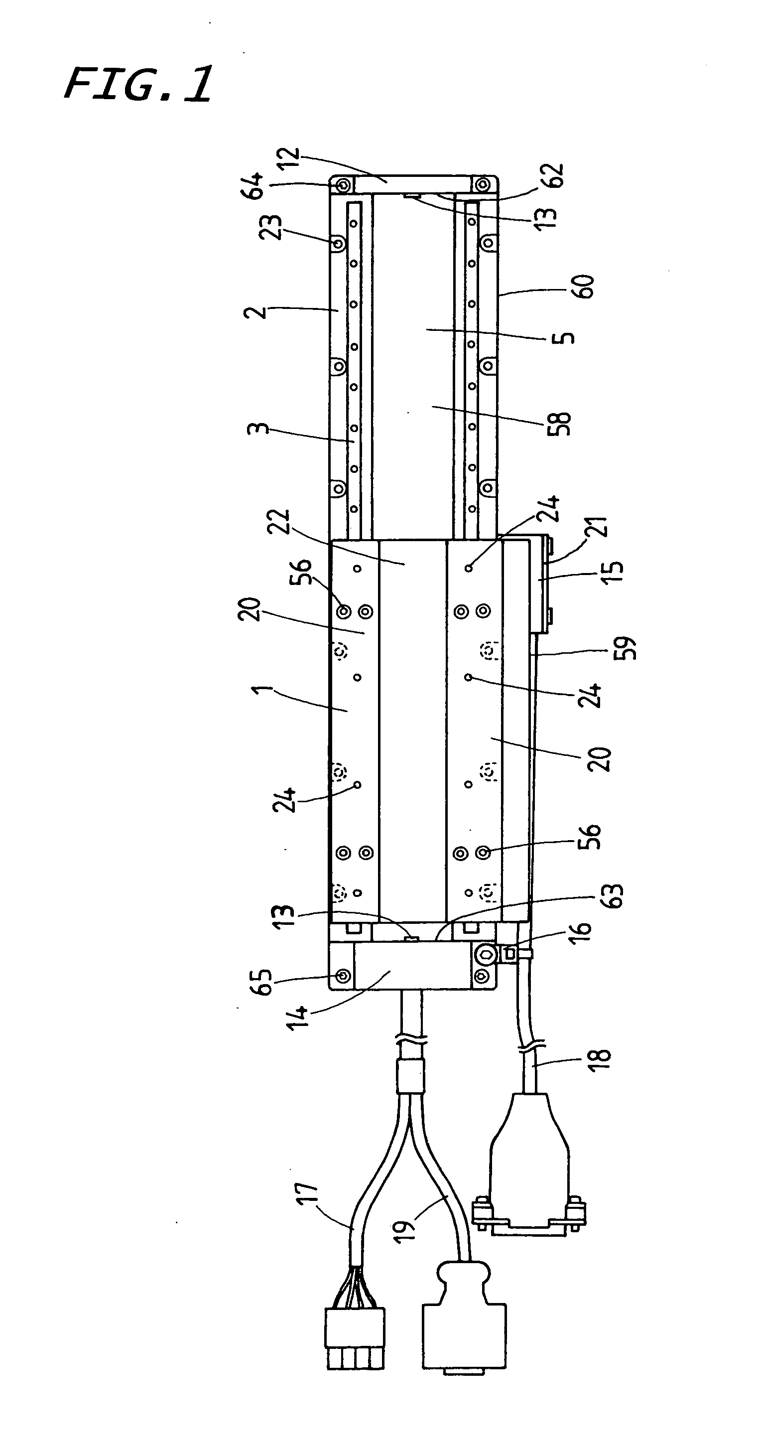
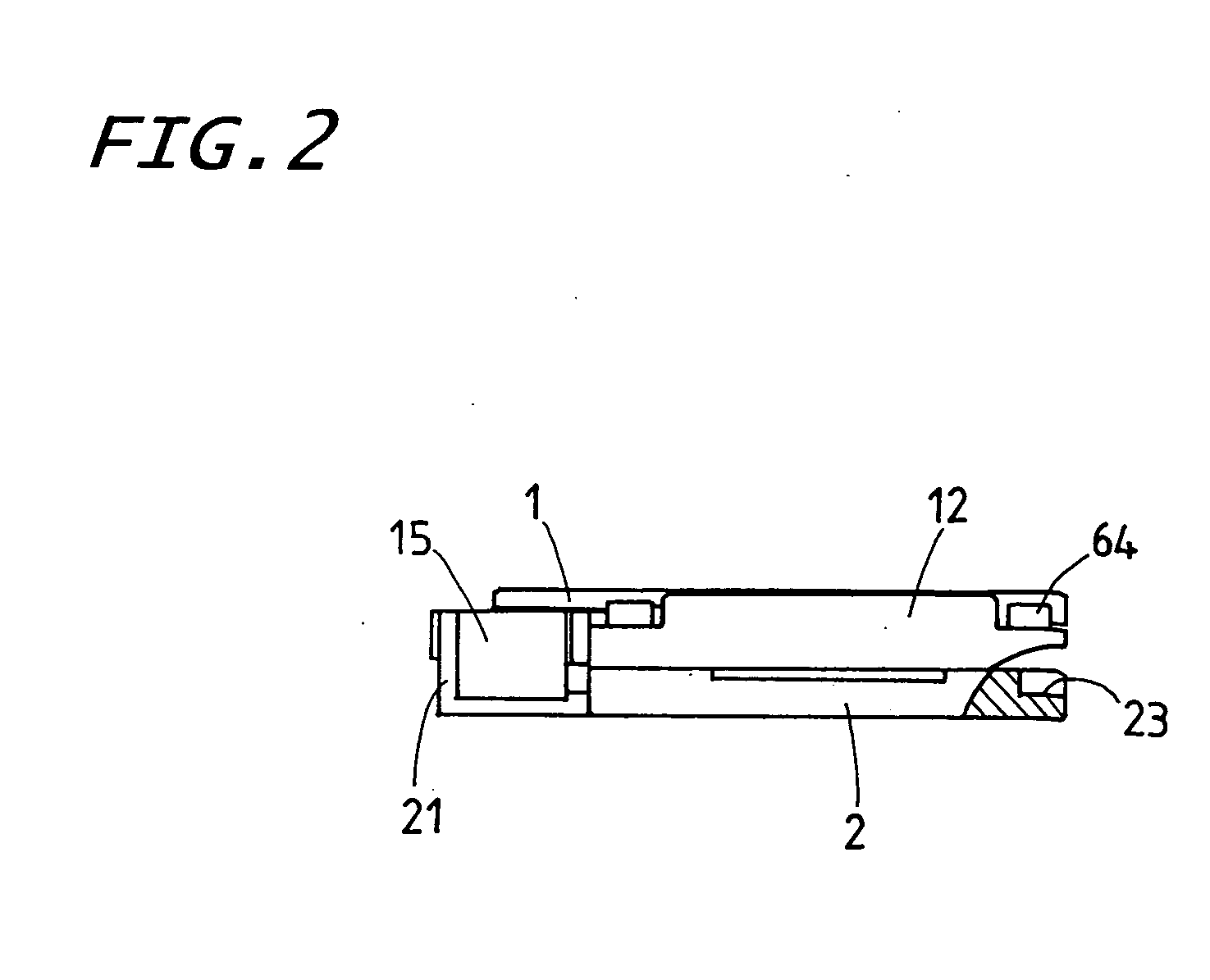
[0041] Preferred embodiments of a sliding device according to the present invention will be explained hereinafter in detail with reference to the accompanying drawings. The sliding device with an onboard moving-magnet linear motor is envisaged incorporating it in a diversity of machinery including semiconductor manufacturing equipments, machine tools, various assembling machines, testing instruments, position-control system, sliding table system, and so on, which are expected to operate in controlled atmosphere including clean room, testing / experimental laboratories, and so on.

[0042] The sliding device of the present invention is envisaged further developing the existing sliding device disclosed in the commonly assigned Japanese Patent Laid-Open No.2002-10617 so as to allow a moving table traveling for reciprocation over longer stroke, even with slim or compact in the overall construction. The sliding device of the present invention, although in common with the existing sliding dev...


PUM


Abstract

A sliding device is provided which is convenient for manufacturing at high production efficiency the small sliding device, which meets the requirements for high propulsion, high response and long traveling stroke. The sliding device includes a field magnet of eight poles lying on the table, and an armature assembly of twelve coreless armature windings of rectangular shape, which are installed on the bed in opposition to the field magnet. The table is made with a recess sinking by a depth not more than a thickness of the field magnet to make it easier to set in place the field magnet.

Description

FIELD OF THE INVENTION [0001] The present invention relates to a sliding device that has been extensively used in fields as diverse as semiconductor industries, various assembling machines, precise measuring / inspection equipments, testing machines, machine tools, and so on. BACKGROUND OF THE INVENTION [0002] Recent sliding devices have been needed to meet anticipated design specifications in extensively increased fields as diverse as semiconductor industries, various assembling machines, precise measuring / inspection equipments, testing machines, machine tools, and so on. An example of the small sliding device with onboard linear motor is disclosed in, for example Japanese Patent Laid-Open No. H09-266659 in which a moving table is made of magnetic material including steel, and so on and is installed thereon with field magnets to serve as a magnet yoke for magnetic circuit, while a stationary bed is also made of magnetic material to serve as a magnet yoke for magnetic circuit of armat...

Claims


Application Information

Patent Timeline
Patent Type & Authority Applications(United States)
IPC IPC(8): H02K41/00H02K41/03
CPCH02K41/03H02K41/031
Inventor KITADE, NORIMITSU
Owner NIPPON THOMPSON
Why Eureka
Try Eureka