Manufacturing method of fuel cell module and manufacturing method of fuel cell

a manufacturing method and fuel cell technology, applied in the direction of cell components, final product manufacturing, sustainable manufacturing/processing, etc., can solve the problems of lowering power generation efficiency, and achieve the effect of convenient manufacturing and convenient manufacturing

Active Publication Date: 2011-12-15
SUMITOMO RIKO CO LTD +1
View PDF13 Cites 15 Cited by
  • Summary
  • Abstract
  • Description
  • Claims
  • Application Information

AI Technical Summary

Benefits of technology

[0040]According to the present invention, a fuel cell module in which a plurality of cell assemblies are stacked can be manufactured conveniently. Also, a fuel cell can be manufactured conveniently using the manufactured fuel cell modules.

Problems solved by technology

Mixing of the gases supplied to the respective electrodes creates issues such as lowered power generation efficiency.

Method used


Image

  • Manufacturing method of fuel cell module and manufacturing method of fuel cell
  • Manufacturing method of fuel cell module and manufacturing method of fuel cell
  • Manufacturing method of fuel cell module and manufacturing method of fuel cell

Examples


first embodiment

[0055][Configuration of Fuel Cell]

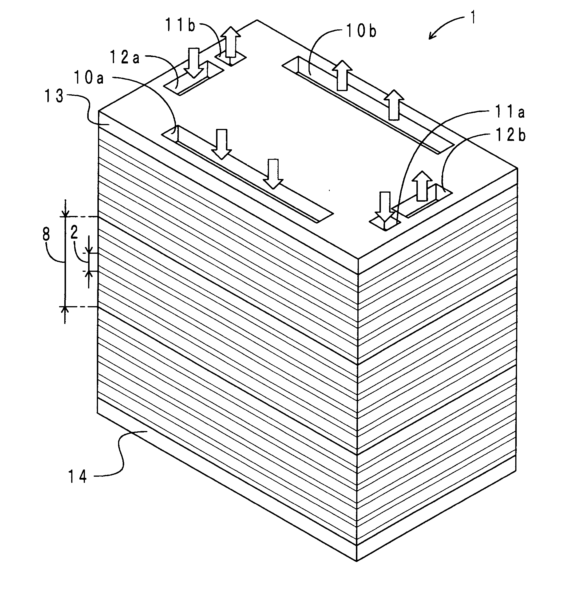
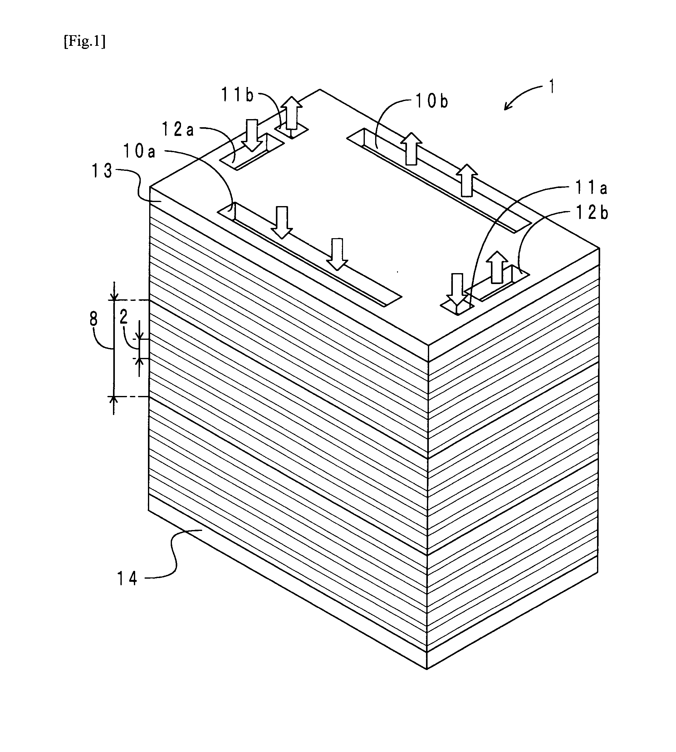
[0056]First, the configuration of a fuel cell including fuel cell modules manufactured in accordance with the manufacturing method of a fuel cell module according to the present embodiment will be described. FIG. 1 is a perspective view of a fuel cell including fuel cell modules manufactured in accordance with the manufacturing method of a fuel cell module according to the present embodiment. As shown in FIG. 1, a fuel cell 1 is structured by stacking three modules 8. Each module 8 is structured by stacking five cell assemblies 2.

[0057]The fuel cell 1 is a proton-exchange membrane fuel cell. A pair of end plates 13, 14 are respectively disposed on both ends of the modules 8 in the stacking direction. The pair of end plates 13, 14 are made of stainless steel, and have a rectangular plate shape. Formed along the four sides of the end plate 13 are an air supply hole 10a that supplies air (oxidizing gas), an air discharge hole 10b that discharges air, a...

second embodiment

[0088]The manufacturing method of a fuel cell module and the manufacturing method of a fuel cell according to the present embodiment are different from those according to the first embodiment in that a seal member preform is integrally formed to match the shape of the peripheral edge portion of the electrode member. Accordingly, the difference will be mainly described herein.

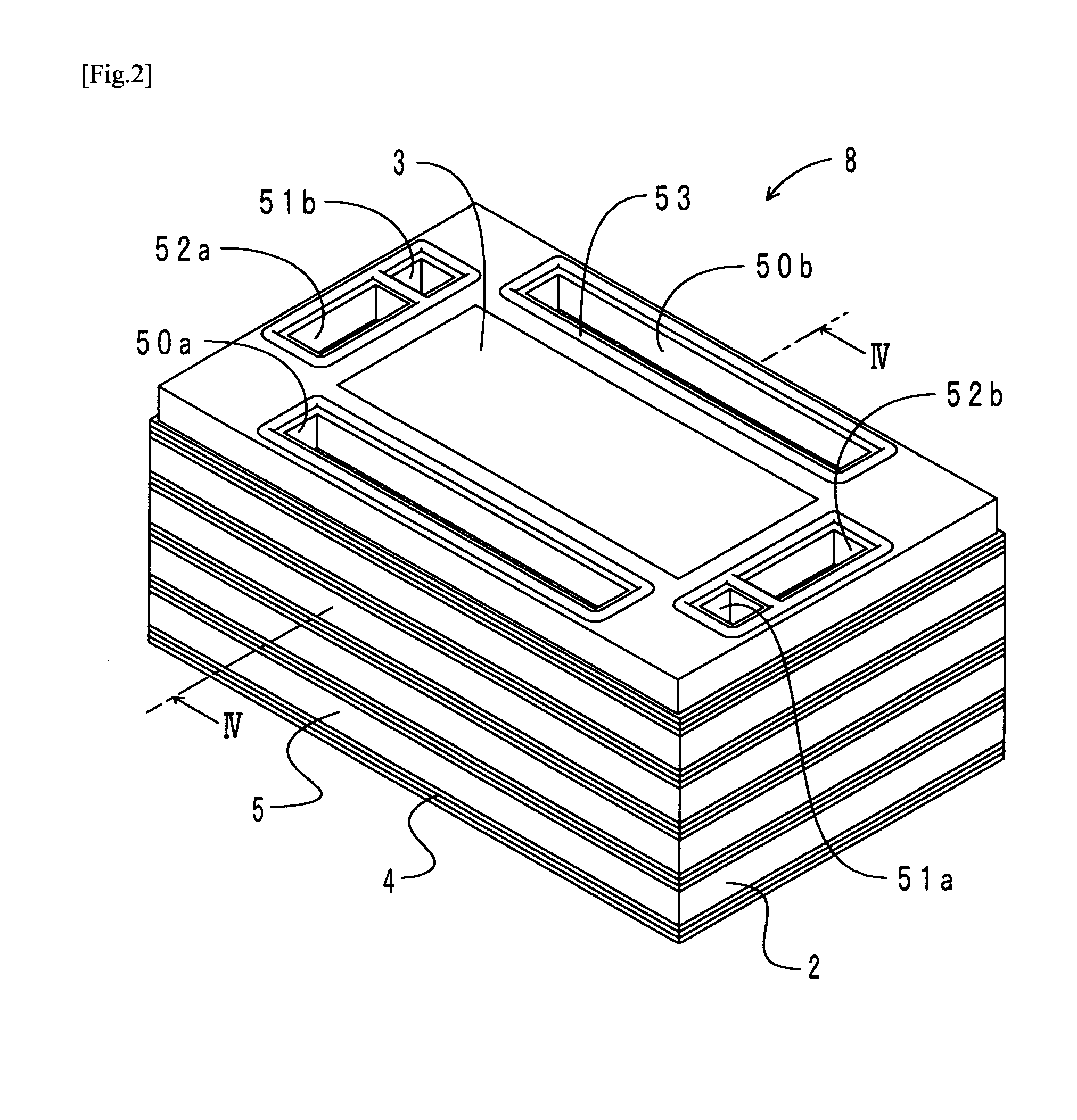
[0089]First, the configuration of a fuel cell module manufactured in accordance with the manufacturing method of a fuel cell module according to the present embodiment will be described. FIG. 9 is a cross-sectional view of a fuel cell module manufactured in accordance with the manufacturing method of a fuel cell module according to the present embodiment. Components in FIG. 9 corresponding to those in FIG. 4 are denoted by the same reference symbols. As shown in FIG. 9, the module 8 is formed by stacking five cell assemblies 2. Each cell assembly 2 includes an electrode member 3, a separator 4, and a seal member...


PUM

PropertyMeasurementUnit
temperatureaaaaaaaaaa
porosityaaaaaaaaaa
porosityaaaaaaaaaa

Abstract

A manufacturing method of a fuel cell module includes: forming an outer divided body having a frame shape and formed from an uncrosslinked item of solid rubber having adhesiveness in a seal member arrangement portion of a separator to produce an outer temporary assembly, and forming an inner divided body having a frame shape and formed from an uncrosslinked item of solid rubber in a peripheral edge portion of an electrode member to produce an inner temporary assembly fitting the inner temporary assembly into a frame of the outer temporary assembly to produce a cell assembly temporary assembly; arranging a cell assembly stack, in which a plurality of the cell assembly temporary assemblies are stacked, in a forming die; and pressurizing and heating the forming die to crosslink the uncrosslinked item.

Description

TECHNICAL FIELD[0001]The present invention relates to a manufacturing method of a fuel cell module in which a plurality of cell assemblies formed by integrating an electrode member and a separator with each other are stacked, and to a manufacturing method of a fuel cell.BACKGROUND ART[0002]A Fuel cell generating electricity from electrochemical reactions of gases has a high power generation efficiency and an extremely small impact on the environment since the discharged gas is clean. Among these, the proton-exchange membrane fuel cell is capable of operating at relatively low temperatures and has a large output density. For this reason, its application to various fields such as power generation and as a power source for automobiles is anticipated.[0003]In the proton-exchange membrane fuel cell, a cell in which separators sandwich a membrane electrode assembly (MEA) or the like serves as the unit of power generation. The MEA is formed from a polymer membrane (electrolyte membrane) ac...

Claims


Application Information

Patent Timeline
Patent Type & Authority Applications(United States)
IPC IPC(8): H01M8/00H01M50/184H01M50/186H01M50/193H01M50/403
CPCH01M8/0273H01M8/0276H01M8/0284H01M8/0286H01M8/0247Y02E60/521H01M8/1002H01M8/249H01M8/242H01M8/1007H01M8/00Y02P70/50Y02E60/50Y02E60/10H01M50/403H01M8/2483H01M8/2404H01M8/2457H01M50/184H01M50/186H01M50/193Y02T90/40H01M2250/20
Inventor TANAHASHI, HIDEAKIHAGA, SHINICHIKADONO, HIDEYAISHIOKA, YUTAKASATO, KENJISHIZUKU, FUMISHIGEYOSHIKAWA, HIROO
Owner SUMITOMO RIKO CO LTD
Why Eureka
Try Eureka