
Adjunct device and system for an injector for monitoring injected amounts

a technology of an injector and adjunct device, which is applied in the direction of intravenous devices, other medical devices, drugs and medications, etc., can solve the problems of high voltage generation, high strain, and bending of the piezopolymer

Pending Publication Date: 2020-12-24
G E EHRLICH 1995LTD
View PDF7 Cites 0 Cited by
  • Summary
  • Abstract
  • Description
  • Claims
  • Application Information

AI Technical Summary

Benefits of technology

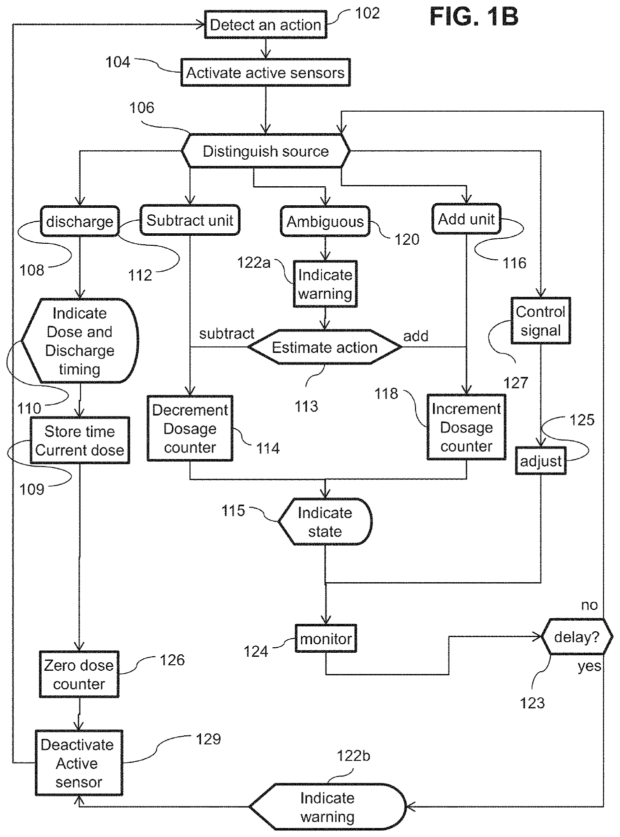
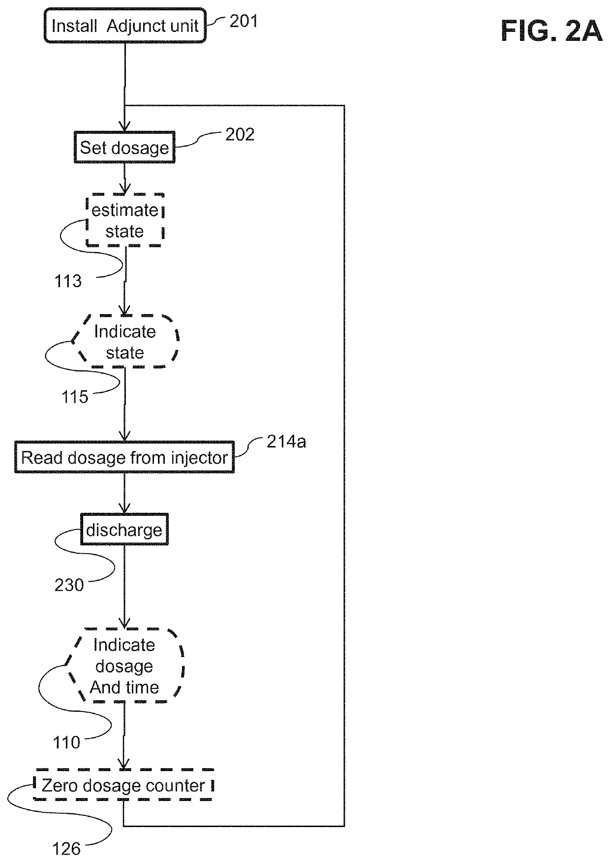
The patent describes a device for tracking the dosage of a pen injector. The device includes a viewport in the injector, a connector for holding a tracking device, and one or more vibration sensors. The vibration sensors measure the movement of the injector and produce an output that is used to adjust a dosage counter. The device can also display the value of the dosage counter for easy viewing by the user. The technical effects of the invention include improved accuracy in tracking dosage and ease of use for users.

Problems solved by technology

As the piezo film is displaced from the mechanical neutral axis, bending creates very high strain within the piezopolymer and therefore high voltages are generated.

Method used


Image

  • Adjunct device and system for an injector for monitoring injected amounts
  • Adjunct device and system for an injector for monitoring injected amounts
  • Adjunct device and system for an injector for monitoring injected amounts

Examples


examples

[0257]Reference is now made to the following examples, which together with the above descriptions illustrate some embodiments of the invention in a non limiting fashion.

[0258]FIGS. 17 and 18 illustrate examples of sensor output from a circumferential axis of a movement sensor mounted on an insulin injector pen. An Analog Device ADXL327 tilt sensing movement sensor was mounted on the ventral side of an Apidara® SoloSTAR® insulin injector pen near the proximal end thereof. Movement was measured during incrementing and decrementing of a dosage of the pen. The movement sensor is described in the Analog Devices ASXL327 specification sheet Rev. 0 published in 2009 by and available from Analog Devices, Inc. One Technology Way, PO. Box 9106 Norwood, Mass. 02062-9106. The sample rate was 10000 / second.

[0259]FIG. 17 illustrates movements caused by incrementing a dosage. The abscissa is time and the ordinate axis is sensor output. A first increment of dosage occurs a 600 ms and a second increme...


PUM


Abstract

In some embodiments, an adjunct device for tracks time and / or dosage of a medicine. The device may include a connector for mounting the device to a deposable pen injector. The device may be configured to allow use of the native controls and injectors of the injector. For example the device may include a view port for viewing a dose indicator of the injector. The device may include one or more vibration sensors. A processor may be configured to differentiate increasing a dose, decreasing a dose and / or discharging the medicine based on the output of the sensors. Optionally a display of the device may be positioned for simultaneous viewing with the dosage indicator of the injector. For example a user may verify the accuracy of the adjunct device before performing a discharge.

Description

RELATED APPLICATION[0001]This application is a Continuation of U.S. patent application Ser. No. 15 / 220,615 filed on Jul. 27, 2016, which claims the benefit of priority under 35 USC 119(e) of U.S. Provisional Patent Application No. 62 / 272,275 filed on Dec. 29, 2015. The contents of the above applications are all incorporated by reference as if fully set forth herein in their entirety.FIELD AND BACKGROUND OF THE INVENTION[0002]The present invention, in some embodiments thereof, relates to an adjunct device and system for an injector, and, more particularly, but not exclusively, to a device to detect and / or indicate times and / or dosages of insulin injections. U.S. Patent Publication No. 2014 / 020010 discloses, “A supplemental device for attachment to an injection device. A supplemental device for attachment to an injection device, the supplemental device comprising: a housing; an electromechanical switch arrangement having an open state and a closed state, the electromechanical switch a...

Claims


Application Information

Patent Timeline
Patent Type & Authority Applications(United States)
IPC IPC(8): A61M5/315G16H20/17
CPCA61M5/31548G16H20/17G16H40/63A61M5/31568A61M2205/33A61M2209/00A61M2205/3576G16H50/70A61M2005/3126A61M2205/50A61M2205/8206A61M2205/52A61M2205/3553A61M2209/04A61M2205/502A61M2205/3569
Inventor MICHAEL, MENASH
Owner G E EHRLICH 1995LTD
Learn More