Traffic signal recognition system
- Summary
- Abstract
- Description
- Claims
- Application Information
AI Technical Summary
Benefits of technology
Problems solved by technology
Method used
Image

Examples
first example
1-3-1. First Example
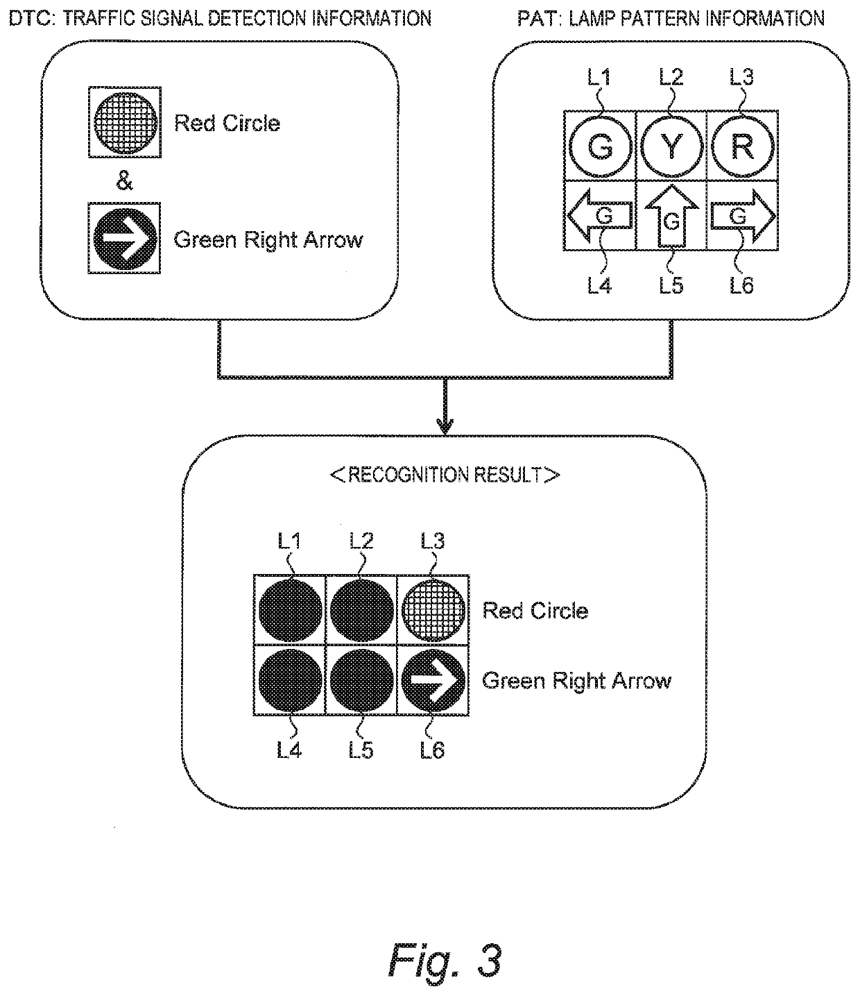
[0060]FIG. 3 is a conceptual diagram for explaining a first example of the lighting state recognition processing. The traffic signal detection information DTC includes information on two detected parts of the subject traffic signal SX. More specifically, the traffic signal detection information DTC indicates the “appearance” of each of the two detected parts of the subject traffic signal SX. In this example, the appearance of the detected part of the subject traffic signal SX includes both the color and the shape (i.e., a lighting shape of a lighting part). The appearance of one of the detected parts is a “red circle”, and the appearance of the other of the detected parts is a “green right arrow.” However, the relative positional relationship between the two detected parts is not known.
[0061]The traffic signal recognition system 10 compares the traffic signal detection information DTC with the lamp pattern information PAT. Then, the traffic signal recognition sys...
second example
1-3-2. Second Example
[0064]FIG. 4 is a conceptual diagram for explaining a second example of the lighting state recognition processing. The traffic signal detection information DTC includes information on two detected parts of the subject traffic signal SX. More specifically, the traffic signal detection information DTC indicates the “relative positional relationship” between the two detected parts in addition to the “appearance” of each of the two detected parts of the subject traffic signal SX. In this example, however, the appearance of the detected part includes only the color, and the shape (i.e., the lighting shape of the lighting part) is unknown. The appearance of one of the detected parts is “red”, the appearance of the other of the detected parts is “green”, and the two detected parts are vertically lined.
[0065]The traffic signal recognition system 10 compares the traffic signal detection information DTC with the lamp pattern information PAT. Then, the traffic signal recog...
third example
1-3-3. Third Example
[0068]FIG. 5 is a conceptual diagram for explaining a third example of the lighting state recognition processing. The traffic signal detection information DTC indicates a rough shape of each of the two detected parts in addition to the contents in the case of the second example (FIG. 4) described above. The appearance of one of the detected parts is a “red circle”, the appearance of the other of the detected parts is a “green arrow”, and the two detected parts are vertically lined. However, a direction of the arrow is unknown.
[0069]As in the case of the second example, a lighting state “L3, L6: lighted; L1, L2, L4, L5: unlighted” is recognized as the lighting state of the subject traffic signal SX. That is, it is recognized that a “red circular signal” and a “green right arrow signal” lined vertically are lighted. Even when the arrow direction is unknown, it is possible to recognize the the lighting state of the subject traffic signal SX with high accuracy by ref...
PUM
 Abstract
Description
Claims
Application Information
 - R&D
- Intellectual Property
- Life Sciences
- Materials
- Tech Scout
- Unparalleled Data Quality
- Higher Quality Content
- 60% Fewer Hallucinations
Browse by: Latest US Patents, China's latest patents, Technical Efficacy Thesaurus, Application Domain, Technology Topic, Popular Technical Reports.
© 2025 PatSnap. All rights reserved.Legal|Privacy policy|Modern Slavery Act Transparency Statement|Sitemap|About US| Contact US: help@patsnap.com