Optical element and authentication medium

Pending Publication Date: 2020-12-31
TOPPAN PRINTING CO LTD
View PDF0 Cites 1 Cited by
  • Summary
  • Abstract
  • Description
  • Claims
  • Application Information

AI Technical Summary

Benefits of technology

[0026]According to the present invention, the authenticity of o

Problems solved by technology

As a result, it takes time for the observer to

Method used


Image

  • Optical element and authentication medium
  • Optical element and authentication medium
  • Optical element and authentication medium

Examples


first embodiment

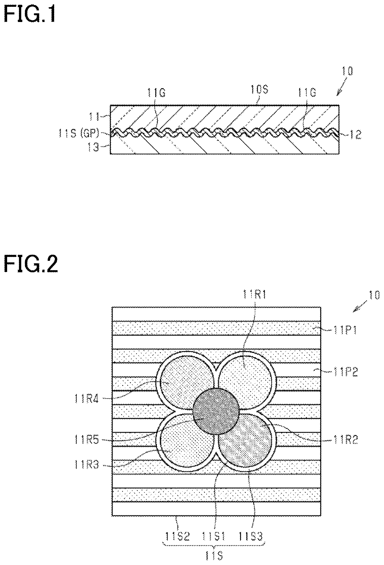
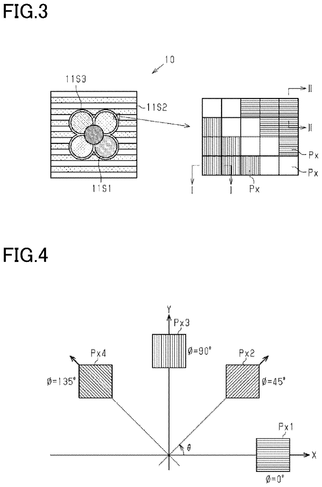
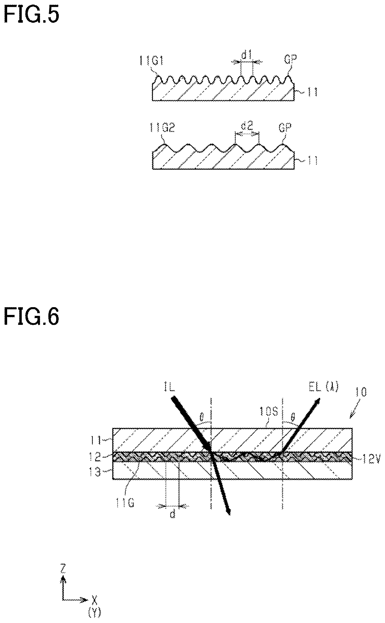
[0098]With reference to FIGS. 1 to 35, a first embodiment of an optical element of the present invention will be described. Throughout the drawings, components that perform the same or similar functions are denoted by the same reference signs, and duplicated description thereof will be omitted. Further, embodiments of the present disclosure are a group of embodiments based on a unique and unitary invention from the background. Further, aspects of the present disclosure are aspects of a group of embodiments based on a single invention. Configurations of the present disclosure may include each aspect of the present disclosure. Features of the present disclosure can be combined with each other and constitute each configuration. Accordingly, features of the present disclosure, configurations of the present disclosure, aspects of the present disclosure, and embodiments of the present disclosure can be combined with each other, and these combinations have synergistic functions and can per...

second embodiment

[0189]With reference to FIGS. 36 to 38, a second embodiment of the optical element will be described. The optical element of the second embodiment of the present invention differs from the optical element of the first embodiment in the shape of the grating pattern included in the grating structure. Therefore, the following description will be given focusing on this difference, while components of the optical element of the second embodiment corresponding to those of the optical element of the first embodiment are denoted by the same reference signs as those of the first embodiment, and the specific description thereof will be omitted. Further, for convenience of illustration, FIGS. 36 to 38 illustrate the grating structure as a structure having an array of the convex portions that protrude in a direction away from the flat surface. In addition, in the optical element of the second embodiment, the color of the grating structure observed by the observer may be based on the diffracted ...

third embodiment

[0228]With reference to FIG. 39, a third embodiment of the optical element will be described. The optical element of the third embodiment of the present invention differs from the optical element 10 of the first embodiment in that the first layer contains a filler. Therefore, the following description will be given focusing on this difference, while the components of the optical element of the third embodiment corresponding to those of the optical element of the first embodiment are denoted by the same reference signs as those of the first embodiment, and specific description thereof will be omitted.

[0229]As shown in FIG. 39, the first layer 11 of an optical element 30 includes a filler 31 dispersed in a resin constituting the first layer 11. The filler 31 has an average particle size of 400 nm or less. At least part of light incident on the first layer 11 is dispersed by the filler dispersed in the first layer 11. Accordingly, the light incident on the grating structure 11G include...


PUM


Abstract

An optical element including a grating structure, and the grating structure including a first grating structure and a second grating structure. A concavo-convex surface includes a first region in which the first grating structure is located, and a second region in which the second grating structure is located and which is located close to the first region in plan view, as viewed perpendicular to the first surface. An azimuth angle of the first grating structure and an azimuth angle of the second grating structure are equal to each other. The first grating structure and the second grating structure have a grating period in a range of 250 nm or more and 500 nm or less, and a difference between the grating period of the first grating structure and the grating period of the second grating structure is 20 nm or more.

Description

CROSS-REFERENCE TO RELATED PATENT APPLICATIONS[0001]This application is a continuation application filed under 35 U.S.C. § 111(a) claiming the benefit under 35 U.S.C. §§ 120 and 365(c) of International Patent Application No. PCT / JP2019 / 011842, filed on Mar. 20, 2019, which is based upon and claims the benefit of priority to Japanese Patent Application No. 2018-053546, filed on Mar. 20, 2018; the disclosures of which are all incorporated herein by reference in their entireties.TECHNICAL FIELD[0002]Embodiments of the present invention relate to optical elements and authentication media.BACKGROUND ARTBackground[0003]For prevention of counterfeiting of valuable securities such as gift certificates, banknotes, and credit cards and brand protection of products, optical elements using holograms, diffraction gratings, multilayer interference films, and the like have been attached to such items. These optical elements, which are not easy to produce, have an effect of preventing counterfeitin...

Claims


Application Information

Patent Timeline
IPC IPC(8): G02B5/18B42D25/328
CPCB42D25/328B42D25/324G02B5/1866G02B5/1809G02B5/1828G02B5/1861
Inventor TASHIRO, TOMOKOSUGIHARA, KEITAROYAMAMOTO, HANAKO
Owner TOPPAN PRINTING CO LTD
Why Eureka
Try Eureka