A corner element for a cage-like structure and a cage-like structure provided with such corner elements

a technology of cage-like structure and corner element, which is applied in the direction of rigid containers, containers, packaging, etc., can solve the problems of unstableness of the entire cage-like structure, and achieve the effect of increasing the stability of the structure and increasing the stability of the corner elemen

Pending Publication Date: 2021-01-07
NEFAB ALFTA
View PDF0 Cites 0 Cited by
  • Summary
  • Abstract
  • Description
  • Claims
  • Application Information

AI Technical Summary

Benefits of technology

[0012]According to another embodiment of the invention each outer wall portion is provided with an aperture configured to receive a strap to be led to and through a corresponding aperture in a said element arranged at the opposite said plane of the structure and to be tightened for increasing the stability of said structure.
[0013]According to another embodiment of the invention the aperture is then located where the outer wall portion is joined to the bottom portion and extends into the bottom portion. This enables comfortable use of straps to further stabilize large structures carrying extremely heavy items when needed.
[0014]According to another embodiment of the invention the bottom portion is provided with through-holes enabling securing of this portion by screws to another member of the structure or a member outside the structure. The stability of a cage-like structure built by using elements according to the invention may by this be further increased by securing the elements in this way.
[0015]According to another embodiment of the invention each outer wall portion is provided with at least one through-hole enabling securing of a said first board-like member thereto by a screw. The advantage of this embodiment is the same as that of the embodiment just mentioned.
[0016]According to another embodiment of the invention each said opening comprises a stop member extending from the bottom portion in parallel with a respective said wall member to form a stop for an end of a said first board-like member introduced through said opening, and the two outer wall portions are connected to each other through the two stop members so that in a said active state of the element an outer recess with a square cross-section as seen perpendicularly to the bottom portion is formed externally of the element along said edge of the structure. This means that the two first board-like members received in the same element will not bear onto each other but onto said stop member, which increases the stability of a corner of a said cage-like structure obtained by use of the element.

Problems solved by technology

It may only be used with said board-like members of one exact thickness, as one example, and as for instance single pieces in a set of wooden planks may have a thickness slightly differing from each other the entire cage-like structure may be unstable.

Method used


Image

  • A corner element for a cage-like structure and a cage-like structure provided with such corner elements
  • A corner element for a cage-like structure and a cage-like structure provided with such corner elements
  • A corner element for a cage-like structure and a cage-like structure provided with such corner elements

Examples


Embodiment Construction

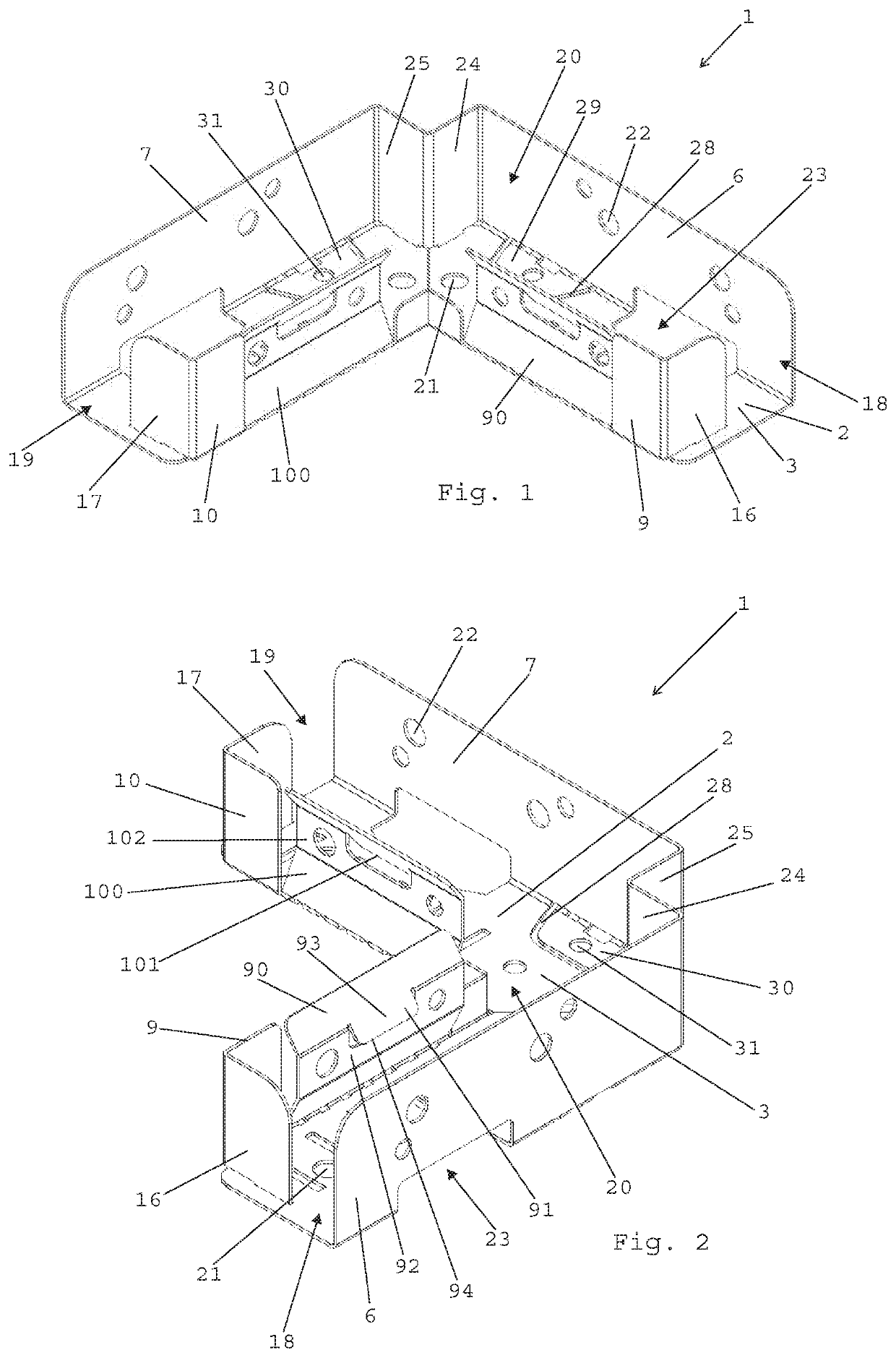
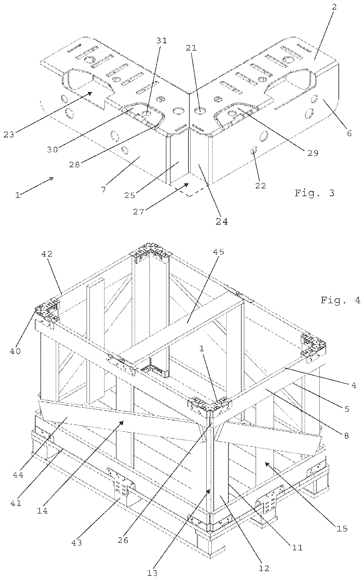
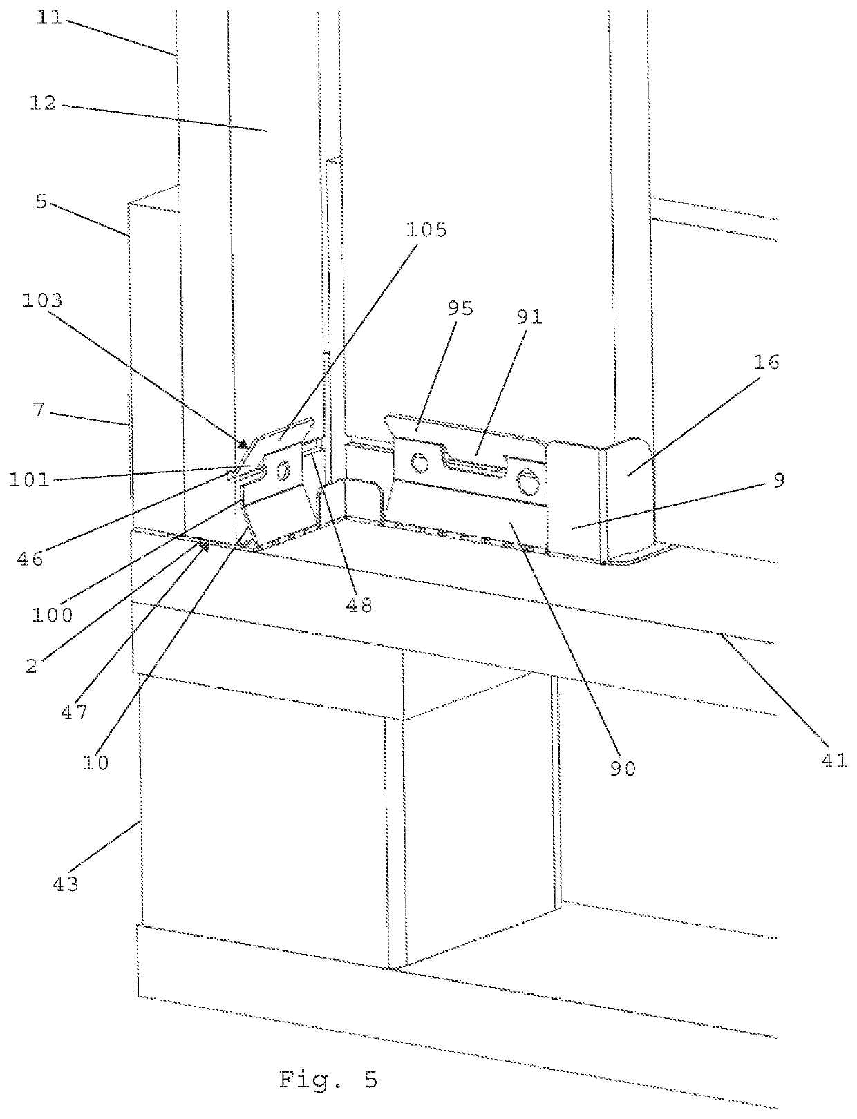
[0029]An element 1 according to an embodiment of the invention will now be described while making reference to FIGS. 1-3 and 5. FIGS. 1 and 2 show the element as it will be arranged on for instance a pallet to form a lower corner of a parallelepipedic cage-like structure, as it is in FIG. 5, whereas FIG. 3 shows the element as it will be arranged to form an upper corner of a said structure. The element 1 is made of one single flat material piece of metal bent to form the element as shown in the figures. The element comprises a bottom portion 2 with a flat surface 3 configured to bear on a thin side 4 of two first board-like members 5, such as wooden planks, of the structure meeting each other at the corner and each extending from the corner along a bottom or a top plane to an adjacent corner of the structure as shown in FIG. 4.

[0030]The element 1 has two outer wall portions 6, 7 to be located externally of the structure in the active state of the element, shown in FIGS. 4 and 5, and...


PUM


Abstract

The invention relates to an element (1) to be arranged in a corner of a parallelepipedic cage-like structure where a bottom or a top plane of the structure meets two walls of the structure extending perpendicularly to this plane and to each other. The element (1) comprises a bottom portion (2), outer wall portions (6, 7), inner wall portions (9, 10) and wall members (16, 17) so as to receive components of said structure in the form of first and second board-like members, such as wooden planks, therebetween with wide sides of these board-like members bearing on each other. The inner wall portions (9, 10) each comprises a spring member (90, 100) configured to bear onto and urge a said second board-like member to press a said first board-like member against an outer wall portion (6, 7), so as to clamp these board-like members between a couple of inner (9, 10) and outer (6, 7) wall portions. The invention also relates to a cage-like structure provided with such elements (1) at said corners thereof.

Description

TECHNICAL FIELD OF THE INVENTION[0001]The present invention relates to an element according to the preamble of claim 1.[0002]Such elements are primarily used to build cage-like structures, such as containers, for transport of larger heavy items, such as larger electric machines, transformers, fuel tanks and the like. The volumes thereof are then several m3 and may even exceed 30 m3. The bottom plane of the structure is then mostly formed by one or several pallets, so that the lower such elements of the structure are then secured to such a pallet. A said cage-like structure typically has board-like members in the form of wooden planks, but may also have one or more such members in the form of for instance plywood boards or board-like members made of plastic.BACKGROUND ART[0003]An element of this type is already known through FR 2 956 384 B1. The element disclosed in that publication requires considerable work to be carried out for adapting other parts of the structure thereto. It may...

Claims


Application Information

Patent Timeline
Patent Type & Authority Applications(United States)
IPC IPC(8): B65D19/38B65D19/16
CPCB65D19/385B65D19/16B65D2519/00432B65D2519/00333B65D2519/00273B65D2519/00502B65D2519/00611B65D2519/00029B65D9/34B65D19/14B65D2519/00064B65D2519/00099B65D2519/00134B65D2519/00169B65D2519/00293B65D2519/00323B65D2519/00452B65D2519/00661B65D9/24B65D19/38B65D2519/00582
Inventor NOWAK, DAVIDNELEN, HANS
Owner NEFAB ALFTA
Why Eureka
Try Eureka