Electrode for a circuit breaker and the circuit breaker

Active Publication Date: 2021-02-04
EATON ELECTRICAL LTD
View PDF0 Cites 0 Cited by
  • Summary
  • Abstract
  • Description
  • Claims
  • Application Information

AI Technical Summary

Benefits of technology

The present disclosure provides an electrode for a circuit breaker and a circuit breaker with the improved electrode design. The electrode eliminates the disadvantages of prior art designs. The electrode includes an electrical terminal, a stationary contact, a movable contact, an arc chute, and a magnetic member. The movable contact has a first contact end and a second contact end, and the magnetic member is positioned between the first contact end and the second contact end. The magnetic member generates a magnetic field force to push the arc formed between the movable and stationary contacts towards the arc chute. The electrode includes a first insert to receive the magnetic member and a second insert to further direct the magnetic field force towards the arc chute. The circuit breaker has a plurality of electrodes connected in series for improved circuit protection. The technical effects are improved arc extinguishment, reduced energy consumption, and more efficient circuit protection.

Problems solved by technology

The existing circuit breaker generally has good performance when alternating-current short-circuited current is disconnected, and often cannot achieve satisfactory effect when direct-current short-circuited current is disconnected.
However, since the current in the direct-current circuit is constant, the “zero-off” phenomenon does not occur, and therefore it is obviously impossible to obtain a good effect by applying the same circuit breaker to the direct-current circuit as those applied in the alternating-current circuit.
Since the structure of the breaking circuit in the circuit breaker mainly includes electrodes, it is also an urgent problem to provide an improved electrode.

Method used


Image

  • Electrode for a circuit breaker and the circuit breaker
  • Electrode for a circuit breaker and the circuit breaker
  • Electrode for a circuit breaker and the circuit breaker

Examples


Embodiment Construction

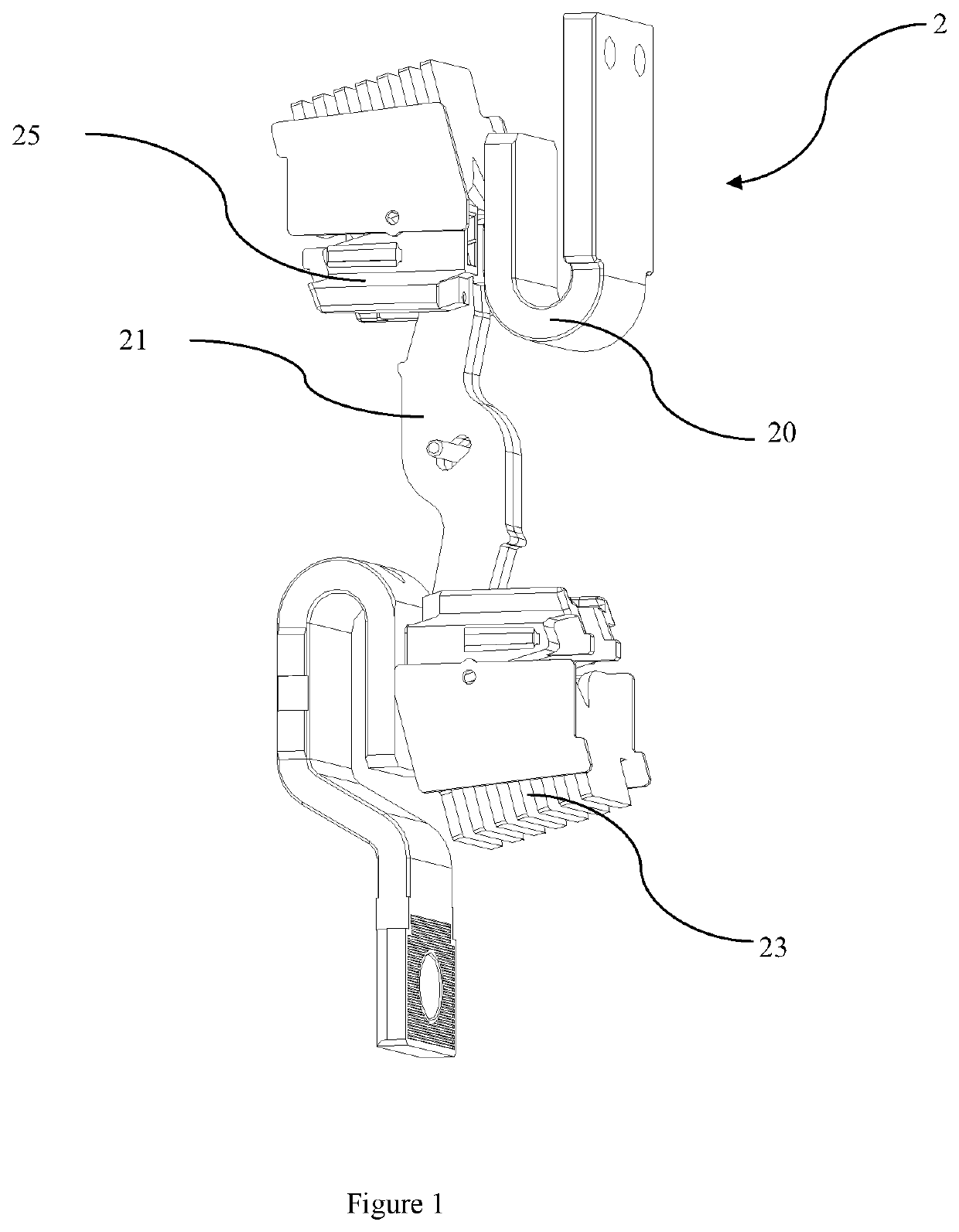
[0025]An exemplary solution of an electrode for a circuit breaker and the circuit breaker according to the present disclosure will now be described in detail with reference to the accompanying drawings. The drawings are provided to present various embodiments of the present disclosure, but are not necessarily drawn to scale of specific embodiments, and certain features may be exaggerated, removed, or partially broken away to better illustrate and explain the disclosure of the present disclosure. Some of the components in the drawings can be adjusted in location according to actual requirements without affecting technical effects. The appearances of the phrase “in the drawings” or similar language in the specification are not necessarily referring to all the figures or examples.

[0026]Certain directional terms used hereinafter to describe the drawings, such as “inner”, “outer”, “upper”, “lower”, and other directional terms, will be understood with their normal meaning and refer to tho...


PUM


Abstract

The disclosure relates to the field of circuit breakers, in particular to an electrode for a circuit breaker and the circuit breaker, wherein the electrode includes an electrical terminal configured to input and output electrical power to the electrode, a stationary contact electrically connected to the electrical terminal and fixed to the electrical terminal, a movable contact configured to rotatably engage the stationary contact, an arc chute arranged on the electrical terminal and adjacent to the stationary contact, and a magnetic member arranged to generate a magnetic field force when the movable contact is disconnected from the stationary contact so as to push an arc formed between the movable contact and the stationary contact towards the arc chute.

Description

CROSS REFERENCE TO RELATED APPLICATIONS[0001]This patent application claims the benefit and priority of Chinese Patent Application No. 201921211364.9 filed on Jul. 30, 2019, the disclosure of which is incorporated by reference herein in its entirety as part of the present application.BACKGROUND[0002]The disclosure relates to the technical field of current switches, in particular to an electrode for a circuit breaker and a circuit breaker.[0003]The existing circuit breaker generally has good performance when alternating-current short-circuited current is disconnected, and often cannot achieve satisfactory effect when direct-current short-circuited current is disconnected. As for the alternating-current circuit, since the current circuit is in a sine wave shape, the current passes through a zero point along with the change of the waveform. When a short circuit occurs, namely when an arc exists in the alternating-current circuit, a “zero-off” phenomenon of the circuit occurs, which is ...

Claims


Application Information

Patent Timeline
IPC IPC(8): H01H33/42H02H3/087H01H33/59
CPCH01H33/42H01H33/59H02H3/087H01H9/443H01H1/2041H01H9/302H01H9/346H01H9/345
Inventor GUO, SHUNFENGZHOU, HUILI, ZUHUI
Owner EATON ELECTRICAL LTD
Why Eureka
Try Eureka