This helps you quickly interpret patents by identifying the three key elements:
Problems solved by technology
Method used
Benefits of technology
Benefits of technology
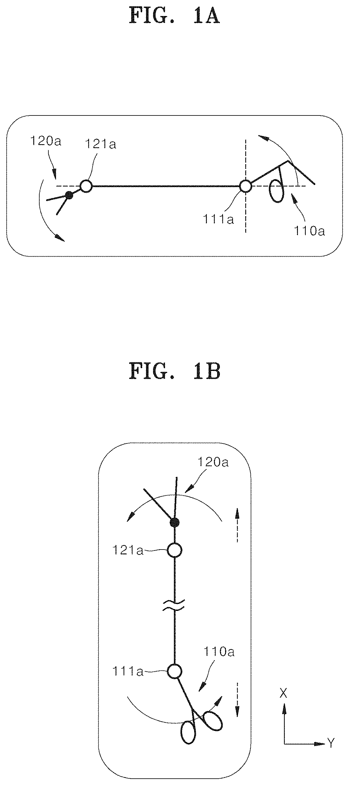
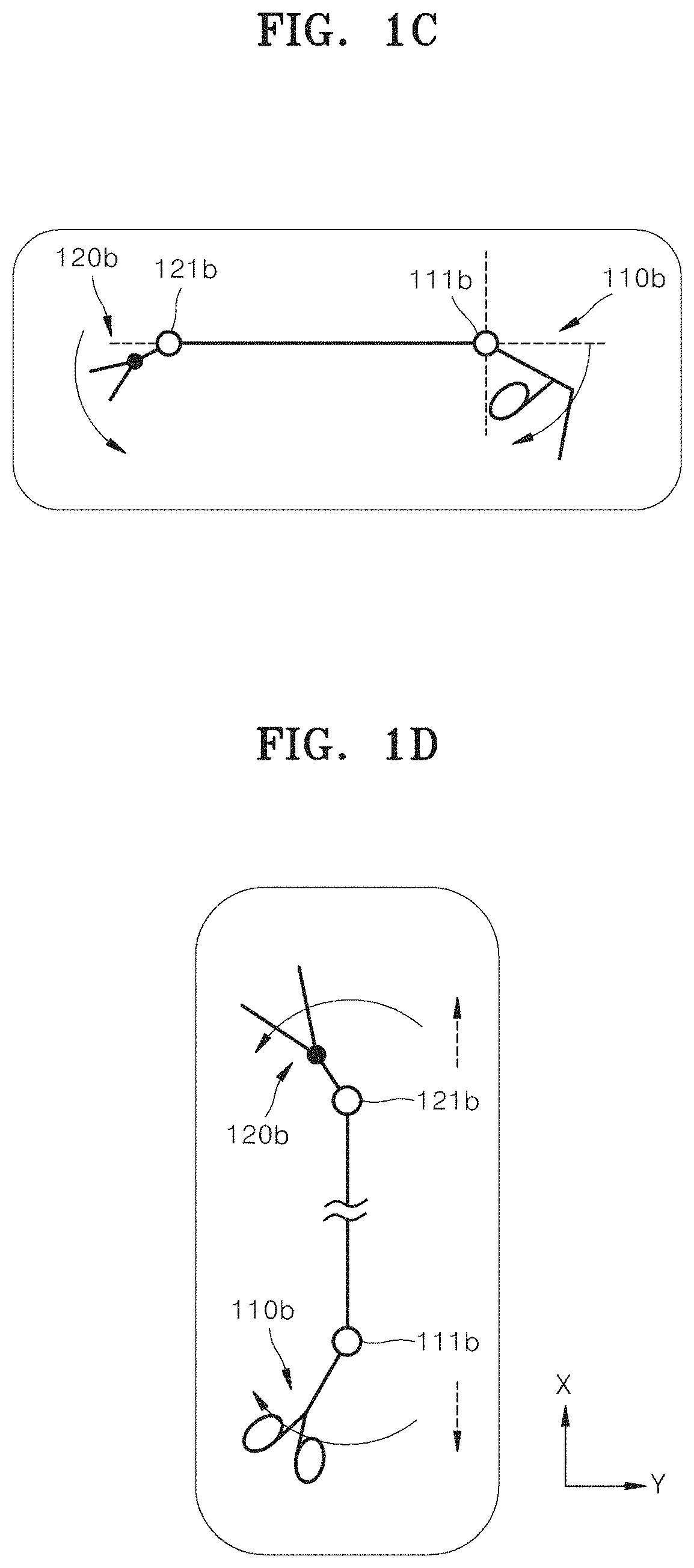
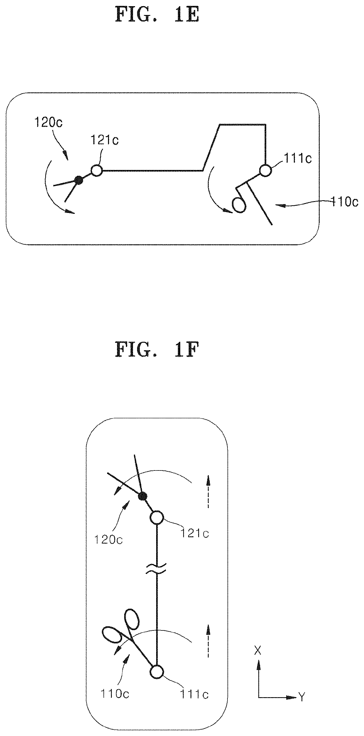
The present invention allows surgeons to operate the manipulation parts of the surgical tool in the same way they would if they were operating the end tool directly, making it easier and more intuitive to perform surgery and improving its accuracy, reliability, and speed.
Problems solved by technology
In particular, open surgery, in which the skin of a surgical site is cut open to cure, shape, or remove an inside organ, causes problems such as bleeding, side effects, pain in patients, or scars.
However, since instruments for surgery of the related art have unbendable end tools, it is difficult to access a surgical site and perform various surgical actions.
However, the operation of a manipulation part for bending the end tool or performing a surgical action does not intuitively match the actual bending of the end tool or the actual surgical action, and thus for surgeons, it is difficult to intuitively handle the instrument for surgery and takes a long time to be able to skillfully use the instrument for surgery.
Method used
Image
Click on the blue label to locate the original text in one second.
Reading with bidirectional positioning of images and text.
Examples
first embodiment
[0013]FIG. 2 is a perspective view illustrating an instrument for surgery according to the present invention.
[0014]FIG. 3 is a side view illustrating the instrument for surgery shown inFIG. 2.
[0015]FIGS. 4 and 5 are perspective views illustrating an end tool of the instrument for surgery shown in FIG. 2.
[0016]FIG. 6A is a plan view illustrating the end tool of the instrument for surgery shown in FIG. 2.
[0017]FIG. 6B is a plan view illustrating an end tool of an instrument for surgery of the related art.
[0018]FIG. 6C is a view illustrating a modification of the end tool shown in FIG. 6A.
[0019]FIG. 6D is a view illustrating a modification of the end tool shown in FIG. 6A.
[0020]FIGS. 7A and 7B are perspective views illustrating a manipulation part of the instrument for surgery shown in FIG. 2.
[0021]FIG. 8 is a schematic view illustrating only a configuration of pulleys and wires of the instrument for surgery shown in FIG. 7, according to the embodiment of the present invention.
[0022]FI...
second embodiment
[0044]FIG. 32 is a perspective view illustrating an instrument for surgery according to the present invention.
[0045]FIG. 33 is an inside perspective view illustrating the instrument for surgery shown in FIG. 32.
[0046]FIG. 34 is a side view illustrating the instrument for surgery shown in FIG. 33.
[0047]FIGS. 35 and 36 are perspective views illustrating a manipulation part of the instrument for surgery shown in FIG. 33.
[0048]FIGS. 37 and 38 are perspective views illustrating a yaw motion of the instrument for surgery shown in FIG. 33.
[0049]FIGS. 39 and 40 are perspective views illustrating an actuation motion of the instrument for surgery shown in FIG. 33.
third embodiment
[0050]FIG. 41 is a perspective view illustrating an instrument for surgery according to the present invention.
[0051]FIG. 42 is a side view illustrating the instrument for surgery shown in FIG. 41.
[0052]FIG. 43 is a perspective view illustrating a manipulation part of the instrument for surgery shown in FIG. 42.
[0053]FIGS. 44 and 45 are perspective views illustrating a yaw motion of the instrument for surgery shown in FIG. 41.
[0054]FIGS. 46 and 47 are perspective views illustrating an actuation motion of the instrument for surgery shown in FIG. 41.
PUM
Abstract
Provided is an instrument for surgery and, more specifically, to an instrument for surgery which can be manually operated in order to be used for laparoscopic surgery or various types of surgery.
Description
TECHNICAL FIELD[0001]The present invention relates to an instrument for surgery and, more specifically, to an instrument for surgery which may be manually operated for laparoscopic surgery or various other types of surgery.BACKGROUND ART[0002]Surgical operations refer to medical operations for curing disease by cutting, incising, or processing the skin, mucous membranes, or other tissue using medical instruments. In particular, open surgery, in which the skin of a surgical site is cut open to cure, shape, or remove an inside organ, causes problems such as bleeding, side effects, pain in patients, or scars. Therefore, as alternatives, a surgical operation, which is performed by forming a hole through the skin and inserting into the hole only a medical instrument such as a laparoscope, a surgical instrument, or a microscope for microsurgery, or a robotic surgical operation, have recently been favored.[0003]Instruments for surgery are tools for performing an operation on a surgical sit...
Claims
Application Information
Patent Timeline
Application Date:The date an application was filed.
Publication Date:The date a patent or application was officially published.
First Publication Date:The earliest publication date of a patent with the same application number.
Issue Date:Publication date of the patent grant document.
PCT Entry Date:The Entry date of PCT National Phase.
Estimated Expiry Date:The statutory expiry date of a patent right according to the Patent Law, and it is the longest term of protection that the patent right can achieve without the termination of the patent right due to other reasons(Term extension factor has been taken into account ).
Invalid Date:Actual expiry date is based on effective date or publication date of legal transaction data of invalid patent.

