Instrument for surgery

a technology for surgical instruments and surgical operations, applied in the field of surgical instruments, can solve the problems of difficult intuitive handling of surgical instruments, difficult to access surgical sites and perform various surgical actions, bleeding, side effects, etc., and achieve the effects of improving accuracy, speed, and convenience of surgery

Active Publication Date: 2018-04-26
LIVSMED INC
View PDF0 Cites 23 Cited by
  • Summary
  • Abstract
  • Description
  • Claims
  • Application Information

AI Technical Summary

Benefits of technology

[0009]According to the present invention, a direction in which a surgeon handles the manipulation part is intuitively identical to a direction in which the end tool is operated. Therefore, surgeons may conveniently perform surgery, and the accuracy, reliability, and speed of surgery may be improved.

Problems solved by technology

In particular, open surgery, in which the skin of a surgical site is cut open to cure, shape, or remove an inside organ, causes problems such as bleeding, side effects, pain in patients, or scars.
However, since instruments for surgery of the related art have unbendable end tools, it is difficult to access a surgical site and perform various surgical actions.
However, the operation of a manipulation part for bending the end tool or performing a surgical action does not intuitively match the actual bending of the end tool or the actual surgical action, and thus for surgeons, it is difficult to intuitively handle the instrument for surgery and takes a long time to be able to skillfully use the instrument for surgery.

Method used


Image

  • Instrument for surgery
  • Instrument for surgery
  • Instrument for surgery

Examples


first embodiment

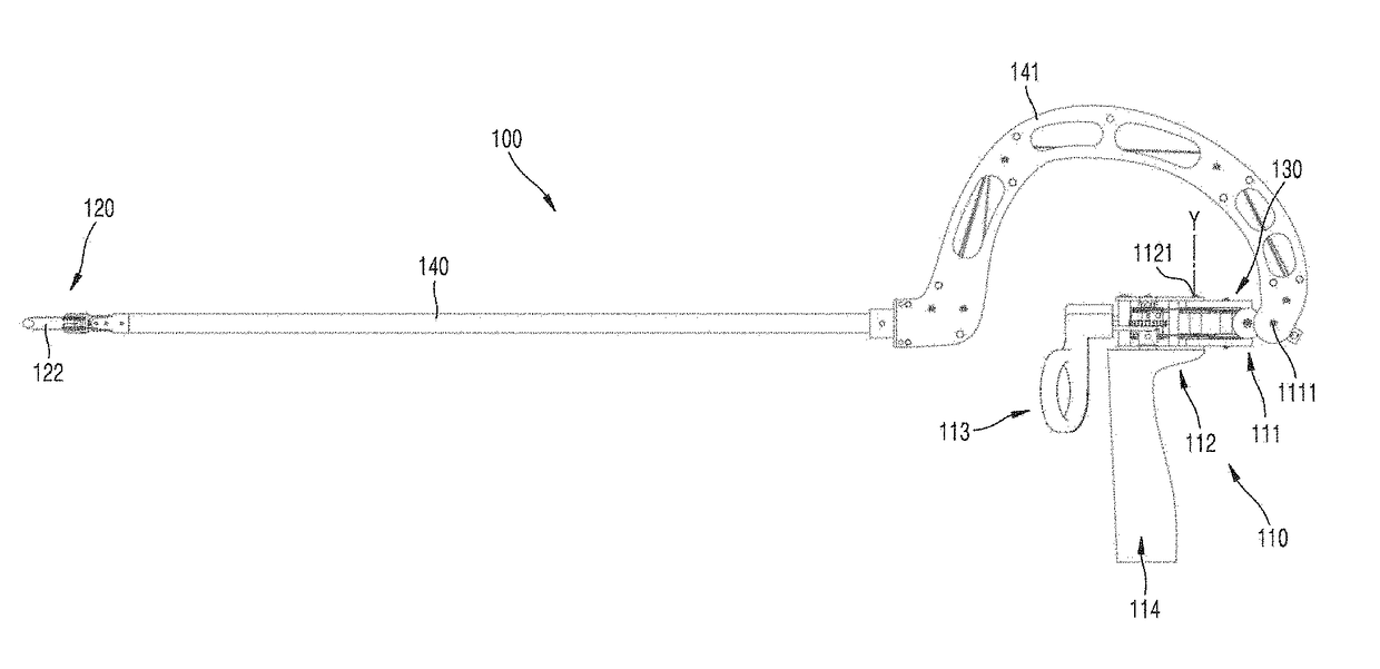
[0013]FIG. 2 is a perspective view illustrating an instrument for surgery according to the present invention.

[0014]FIG. 3 is a side view illustrating the instrument for surgery shown in FIG. 2.

[0015]FIGS. 4 and 5 are perspective views illustrating an end tool of the instrument for surgery shown in FIG. 2.

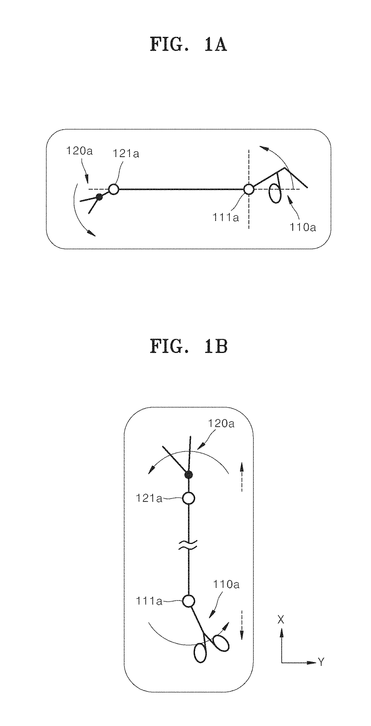
[0016]FIG. 6A is a plan view illustrating the end tool of the instrument for surgery shown in FIG. 2.

[0017]FIG. 6B is a plan view illustrating an end tool of an instrument for surgery of the related art.

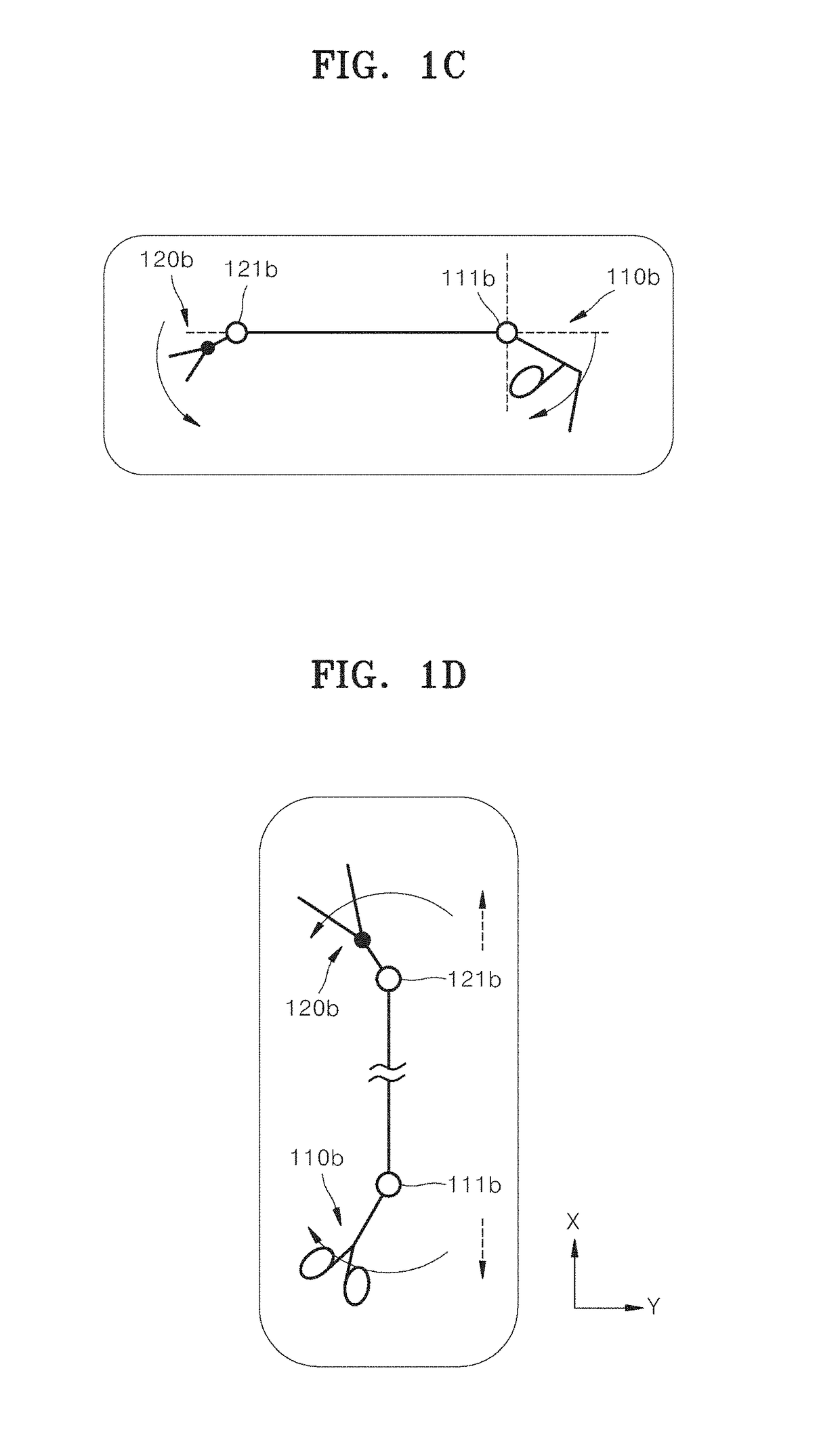
[0018]FIG. 6C is a view illustrating a modification of the end tool shown in FIG. 6A.

[0019]FIG. 6D is a view illustrating a modification of the end tool shown in FIG. 6A.

[0020]FIGS. 7A and 7B are perspective views illustrating a manipulation part of the instrument for surgery shown in FIG. 2.

[0021]FIG. 8 is a schematic view illustrating only a configuration of pulleys and wires of the instrument for surgery shown in FIG. 7, according to the embodiment of the present invention.

[0022]F...

second embodiment

[0044]FIG. 32 is a perspective view illustrating an instrument for surgery according to the present invention.

[0045]FIG. 33 is an inside perspective view illustrating the instrument for surgery shown in FIG. 32.

[0046]FIG. 34 is a side view illustrating the instrument for surgery shown in FIG. 33.

[0047]FIGS. 35 and 36 are perspective views illustrating a manipulation part of the instrument for surgery shown in FIG. 33.

[0048]FIGS. 37 and 38 are perspective views illustrating a yaw motion of the instrument for surgery shown in FIG. 33.

[0049]FIGS. 39 and 40 are perspective views illustrating an actuation motion of the instrument for surgery shown in FIG. 33.

third embodiment

[0050]FIG. 41 is a perspective view illustrating an instrument for surgery according to the present invention.

[0051]FIG. 42 is a side view illustrating the instrument for surgery shown in FIG. 41.

[0052]FIG. 43 is a perspective view illustrating a manipulation part of the instrument for surgery shown in FIG. 42.

[0053]FIGS. 44 and 45 are perspective views illustrating a yaw motion of the instrument for surgery shown in FIG. 41.

[0054]FIGS. 46 and 47 are perspective views illustrating an actuation motion of the instrument for surgery shown in FIG. 41.


PUM


Abstract

The present invention relates to an instrument for surgery and, more specifically, to an instrument for surgery which can be manually operated in order to be used for laparoscopic surgery or various types of surgery.

Description

TECHNICAL FIELD[0001]The present invention relates to an instrument for surgery and, more specifically, to an instrument for surgery which may be manually operated for laparoscopic surgery or various other types of surgery.BACKGROUND ART[0002]Surgical operations refer to medical operations for curing disease by cutting, incising, or processing the skin, mucous membranes, or other tissue using medical instruments. In particular, open surgery, in which the skin of a surgical site is cut open to cure, shape, or remove an inside organ, causes problems such as bleeding, side effects, pain in patients, or scars. Therefore, as alternatives, a surgical operation, which is performed by forming a hole through the skin and inserting into the hole only a medical instrument such as a laparoscope, a surgical instrument, or a microscope for microsurgery, or a robotic surgical operation, have recently been favored.[0003]Instruments for surgery are tools for performing an operation on a surgical sit...

Claims


Application Information

Patent Timeline
Patent Type & Authority Applications(United States)
IPC IPC(8): A61B34/00A61B17/00A61B17/29
CPCA61B34/71A61B17/00234A61B17/2909A61B2017/00323A61B2017/00477A61B2017/00738A61B2017/00438A61B2017/2904A61B2017/2911A61B2017/294A61B2017/2944A61B2017/2923A61B2017/00424A61B2017/291A61B2017/2908
Inventor LEE, JUNG JOOKIM, HEE JIN
Owner LIVSMED INC
Why Eureka
Try Eureka