Lubricant drain conduit for gas turbine engine

a gas turbine engine and drain conduit technology, applied in the direction of engine fuctions, gear lubrication/cooling, jet propulsion plants, etc., can solve the problems of excessive leaking of lubricant and unavoidable leakage of lubrican

Active Publication Date: 2021-02-18
PRATT & WHITNEY CANADA CORP
View PDF0 Cites 3 Cited by
  • Summary
  • Abstract
  • Description
  • Claims
  • Application Information

AI Technical Summary

Problems solved by technology

However, leaks might be unavoidable and, in some cases, leaking lubricant may be excessive, which is undesirable.

Method used


Image

  • Lubricant drain conduit for gas turbine engine

Examples


Embodiment Construction

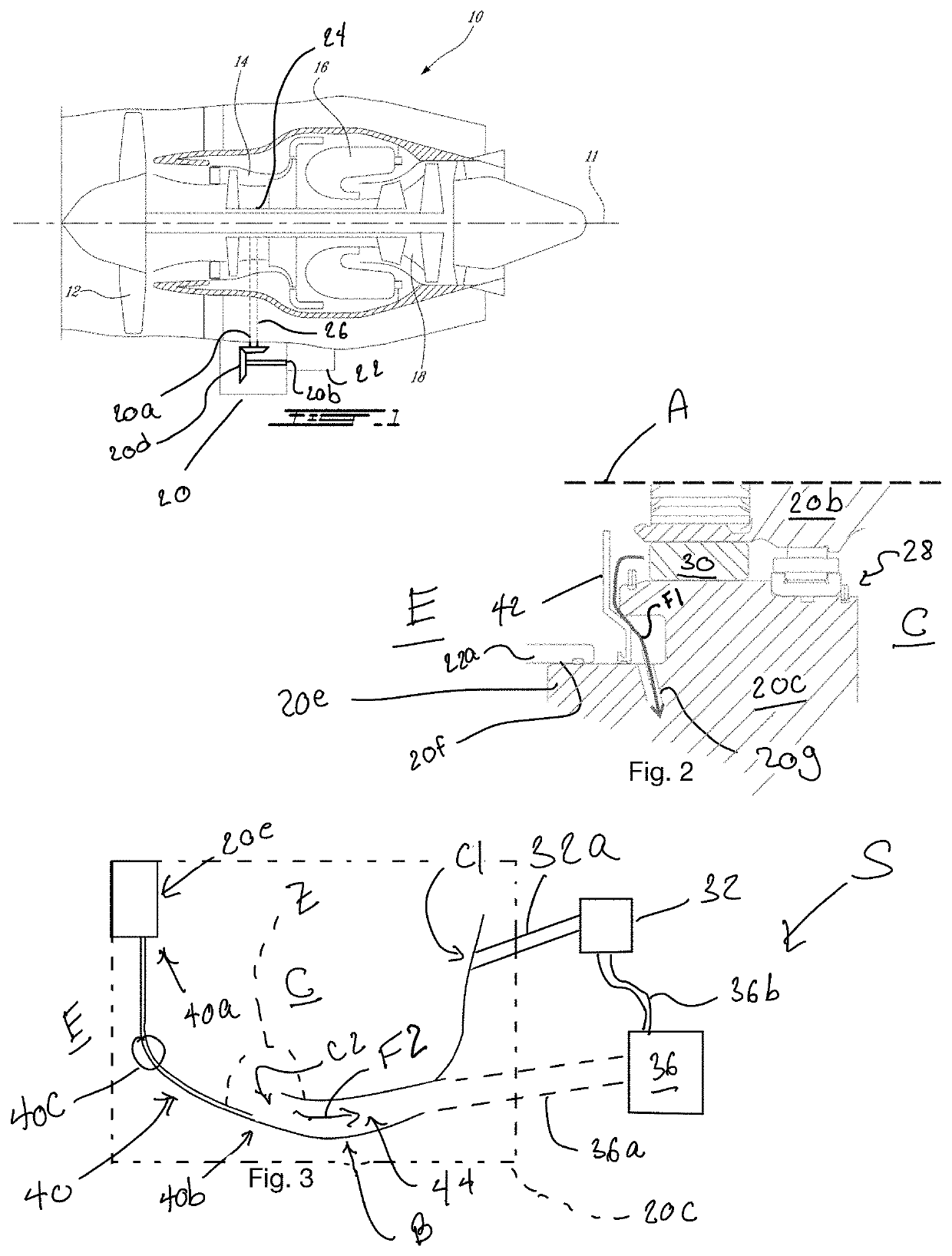
[0010]FIG. 1 illustrates a gas turbine engine 10 of a type preferably provided for use in subsonic flight, generally comprising in serial flow communication a fan 12 through which ambient air is propelled, a compressor section 14 for pressurizing the air, a combustor 16 in which the compressed air is mixed with fuel and ignited for generating an annular stream of hot combustion gases, and a turbine section 18 for extracting energy from the combustion gases. The fan 12, the compressor section 14, and the turbine section 18 are rotatable about a central axis 11 of the engine 10.

[0011]Still referring to FIG. 1, the gas turbine engine 10 may include a gearbox 20 that may be in driving engagement with an accessory 22, such as a pump, a generator, or any suitable accessory. The gearbox 20 has an input 20a that may be in driving engagement with a shaft 24 of the gas turbine engine 10 via an accessory shaft 26. Though not shown for simplicity, a gear arrangement may be present between shaft...


PUM


Abstract

An assembly for a gas turbine engine having: static and rotating components; a seal between the static and rotating components, and between a cavity and an environment outside thereof, the cavity having an inlet fluidly connectable to a source of lubricant and an outlet fluidly connectable to a scavenge pump for drawing lubricant out of the cavity; and a drain conduit having a drain inlet outside the cavity in proximity to the seal for receiving leaked lubricant, and a drain outlet fluidly connected to the outlet of the cavity, the drain outlet located in proximity to a scavenge inlet via which the lubricant exits the cavity to flow toward the scavenge pump such that, in use, a lubricant flow within the drain conduit is entrained by the lubricant exiting the cavity via the scavenge inlet.

Description

TECHNICAL FIELD[0001]The application relates generally to gas turbine engines and, more particularly, to lubrication of components in such engines.BACKGROUND OF THE ART[0002]A gas turbine engine includes a plurality of seals. Such seals may be used to limit lubricant from leaking out of a lubricated cavity, such as a bearing cavity. However, leaks might be unavoidable and, in some cases, leaking lubricant may be excessive, which is undesirable.SUMMARY[0003]In one aspect, there is provided an assembly for a gas turbine engine comprising: static and rotating components; a seal between the static and rotating components, and between a cavity and an environment outside thereof, the cavity having an inlet fluidly connectable to a source of lubricant and an outlet fluidly connectable to a scavenge pump for drawing lubricant out of the cavity; and a drain conduit having a drain inlet outside the cavity in proximity to the seal for receiving leaked lubricant, and a drain outlet fluidly conn...

Claims


Application Information

Patent Timeline
Patent Type & Authority Applications(United States)
IPC IPC(8): F01D25/18F16H57/04
CPCF01D25/18F05D2260/98F16H57/0408F01D25/183F05D2260/602F02C7/36F16H57/0423F16H57/0424F16H57/0441F16H57/0472F16H57/0471F16H57/0438F16H57/0435
Inventor POULIN, MARTINPOWERS, SEAN
Owner PRATT & WHITNEY CANADA CORP
Why Eureka
Try Eureka