Check patentability & draft patents in minutes with Patsnap Eureka AI!

Hybrid structure and method for manufacturing

a hybrid structure and manufacturing method technology, applied in the direction of superstructures, transportation and packaging, other domestic articles, etc., to achieve the effect of good structural integrity and cost-effectiveness

Active Publication Date: 2021-03-18
SABIC GLOBAL TECH BV
View PDF26 Cites 5 Cited by
  • Summary
  • Abstract
  • Description
  • Claims
  • Application Information

AI Technical Summary

Benefits of technology

The patent describes a method of creating a strong and lightweight structure using a hybrid of metal and plastic components. The plastic component wraps around the metal component, creating a secure bond without the need for adhesive. The plastic component can be reinforced with corrugations or holes to strengthen the bond. The hybrid structure allows for complex geometries and the use of high-performance materials. It also allows for the replacement of metal components with plastic ones for weight reduction and cost savings. Overall, the hybrid structure offers improved strength and efficiency while reducing manufacturing costs.

Problems solved by technology

Establishing a connection between two components of dissimilar materials, which connection can withstand the mechanical performance requirements for the automotive industry, or any other industry where safety is of importance, is a challenge.

Method used


Image

  • Hybrid structure and method for manufacturing
  • Hybrid structure and method for manufacturing
  • Hybrid structure and method for manufacturing

Examples


second embodiment

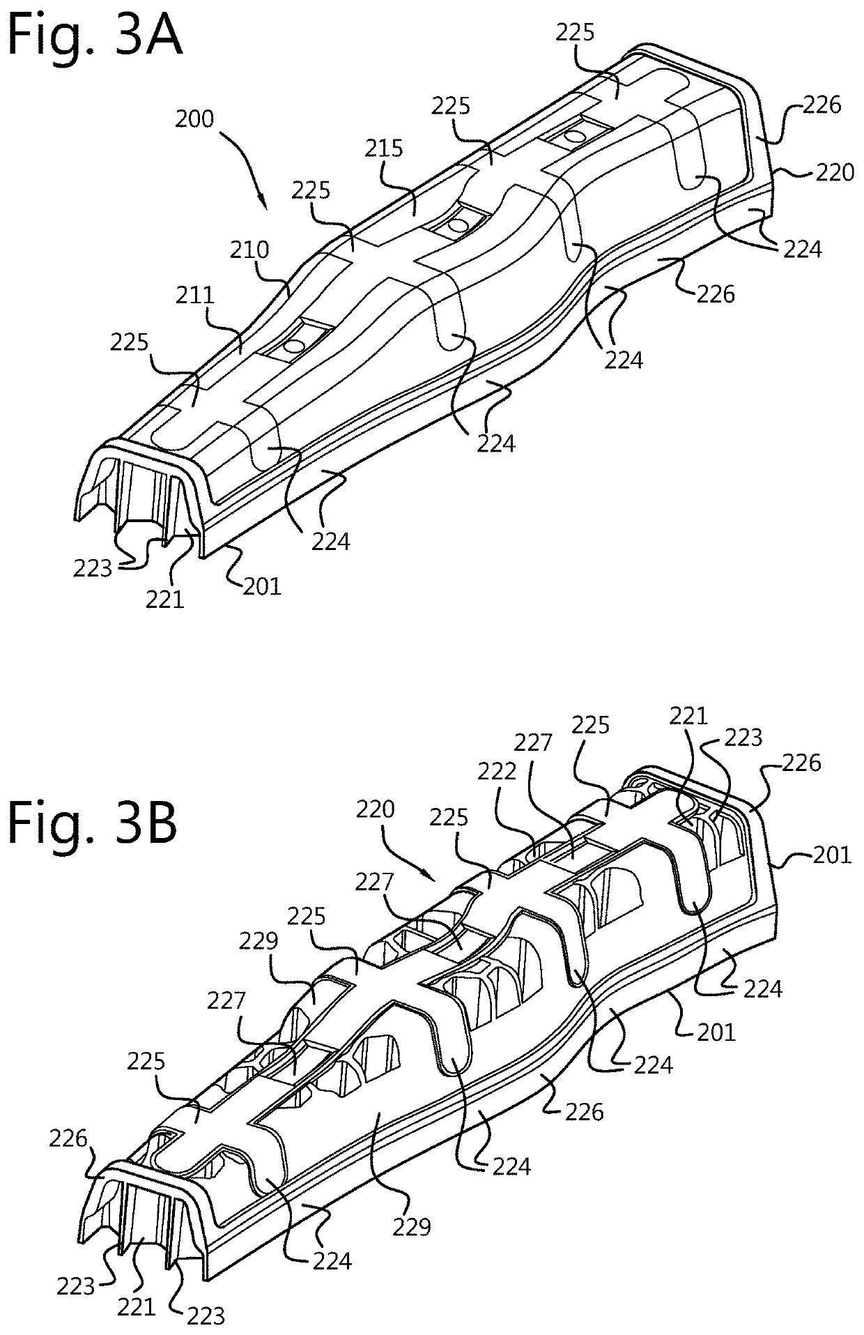
[0054]FIGS. 3a and b show a hybrid structure 200 according to the present invention. The hybrid structure 200 comprises a first component 210 and a thermoplastic second component 220. The first component has a base 211 and two opposite upstanding walls 212 extending from the base 211. The base 211 has a plurality of through holes (see FIG. 5). The upstanding walls 212 have a plurality of further through holes (see FIG. 5), which are aligned with the through holes of the base 211. The first component 210 has an interior 214 that is formed as a channel, as in FIG. 2c. At its exterior 215, the base 211 of the first component 210 is provided with a corrugation, formed as a deepening 218. At its interior 214, the base 211 of the first component 210 is provided with a raised portion (not shown), which is a negative shape of the deepening 218 at the exterior 215. The deepening 218 is provided with branches 218a that extend perpendicularly from the deepening 218 in the base 211 towards the ...

third embodiment

[0058]FIGS. 4a and b show a hybrid structure 300 according to the present invention. The hybrid structure 300 comprises a first component 310 and a thermoplastic second component 320. The first component has a base 311 and two opposite upstanding walls 312 extending from the base 311. The base 311 has a plurality of through holes (see FIG. 5). The upstanding walls 312 have a plurality of further through holes (see FIG. 5), which are aligned with the through holes of the base 311. The first component 310 has an interior 314 that is formed as a channel. At its exterior 315, the base 311 of the first component 310 is provided with a corrugation, formed as a deepening 318. At its interior 314, the base 311 of the first component 310 is provided with a raised portion (not shown), which is a negative shape of the deepening 318 at the exterior 315. The deepening 318 is provided with branches (318a) that extend perpendicularly from the deepening 318 in the base 311 towards the end edges 317...

fourth embodiment

[0064]FIGS. 7a-c show a hybrid structure 400 according to the present invention. The hybrid structure 400 comprises a first component 410 and a thermoplastic second component 420 that extends from the upstanding wall 412 and the base 411 in the longitudinal direction of the first component 410. The first and the second component thus extend in a parallel fashion. The second component 420 comprises a reinforcing portion 421 and a further upstanding wall 428 that delimits the second component 420, and the reinforcing portion 421 in a transverse direction. The reinforcing portion 421 has a honeycomb shaped alveolar structure with channels 422 having an axial direction A perpendicular to the base 411 of the first component. The channels 422 are delimited by cell walls 423.

[0065]Along the base 411 of the first component runs a raised portion 419 in a longitudinal direction, see FIG. 7b. The raised portion 419 has perpendicular branches 419a. Within the raised portion 419 and its branches...


PUM

PropertyMeasurementUnit
angleaaaaaaaaaa
angleaaaaaaaaaa
thicknessaaaaaaaaaa

Abstract

The invention relates to a hybrid structure comprising a first component having a base and an upstanding wall extending from the base, the first component having an interior enclosed between the upstanding wall and the base, and a thermoplastic second component moulded to the first component, the second component comprising a reinforcing portion for structurally reinforcing the first component, the reinforcing portion extending in a longitudinal direction of the first component and located in the interior of the first component, the thermoplastic second component further comprising a locking portion that extends adjacently over at least part of an exterior of the first component, wherein the reinforcing portion and the locking portion are integrally formed, thus interlocking the first component in the thermoplastic second component. The invention relates as well to a method for manufacturing such a hybrid structure, and to a vehicle comprising such a hybrid structure.

Description

BACKGROUND OF THE INVENTIONField of the Invention[0001]The present invention relates to a hybrid structure, specifically a hybrid reinforcing member for reinforcing a part of a body frame of a vehicle. Furthermore, the invention relates to a method for manufacturing such a hybrid structure. Moreover, the invention relates to a vehicle comprising such a hybrid structure.Description of the Related Art[0002]Engineered systems in today's automobiles are often designed and built to meet conflicting and complex requirements. While mobility is a car's primary function, accomplishing that in an energy-efficient manner and ensuring the safety of the occupants are critical requirements. Automotive OEMs, therefore, are aggressively working on making vehicles lighter without compromising its safety. Meeting such complex requirements often requires solutions encompassing innovative designs, manufacturing processes and multi-material systems.[0003]Hybrid systems or structures combining various di...

Claims


Application Information

Patent Timeline
Patent Type & Authority Applications(United States)
IPC IPC(8): B29C45/14B62D29/00
CPCB29C45/14344B29C45/14336B29L2031/3002B29C2045/14327B62D29/004B62D29/043B62D25/04B62D25/06
Inventor DELANEY, MATTHEW MICHAELTREMBLAY, GREGORY E.MUNJURULIMANA, DINESHKARTHIKEYAN, RAJKUMARTIWARI, ANILNAGWANSHI, DHANENDRA KUMARPARAMESHWARA, ARUNACHALA
Owner SABIC GLOBAL TECH BV
Features
  • R&D
  • Intellectual Property
  • Life Sciences
  • Materials
  • Tech Scout
  • Unparalleled Data Quality
  • Higher Quality Content
  • 60% Fewer Hallucinations
Learn More