
Method for determining data rate of user equipment supporting EUDCH service

Active Publication Date: 2007-04-24
SAMSUNG ELECTRONICS CO LTD
View PDF13 Cites 27 Cited by
  • Summary
  • Abstract
  • Description
  • Claims
  • Application Information

AI Technical Summary

Benefits of technology

[0018]It is, therefore, an object of the present invention to provide a method for signaling scheduling information required in performing control scheduling on UEs supporting an enhanced uplink dedicated channel (EUDCH), to a Node B by a UE and a radio network controller.

Problems solved by technology

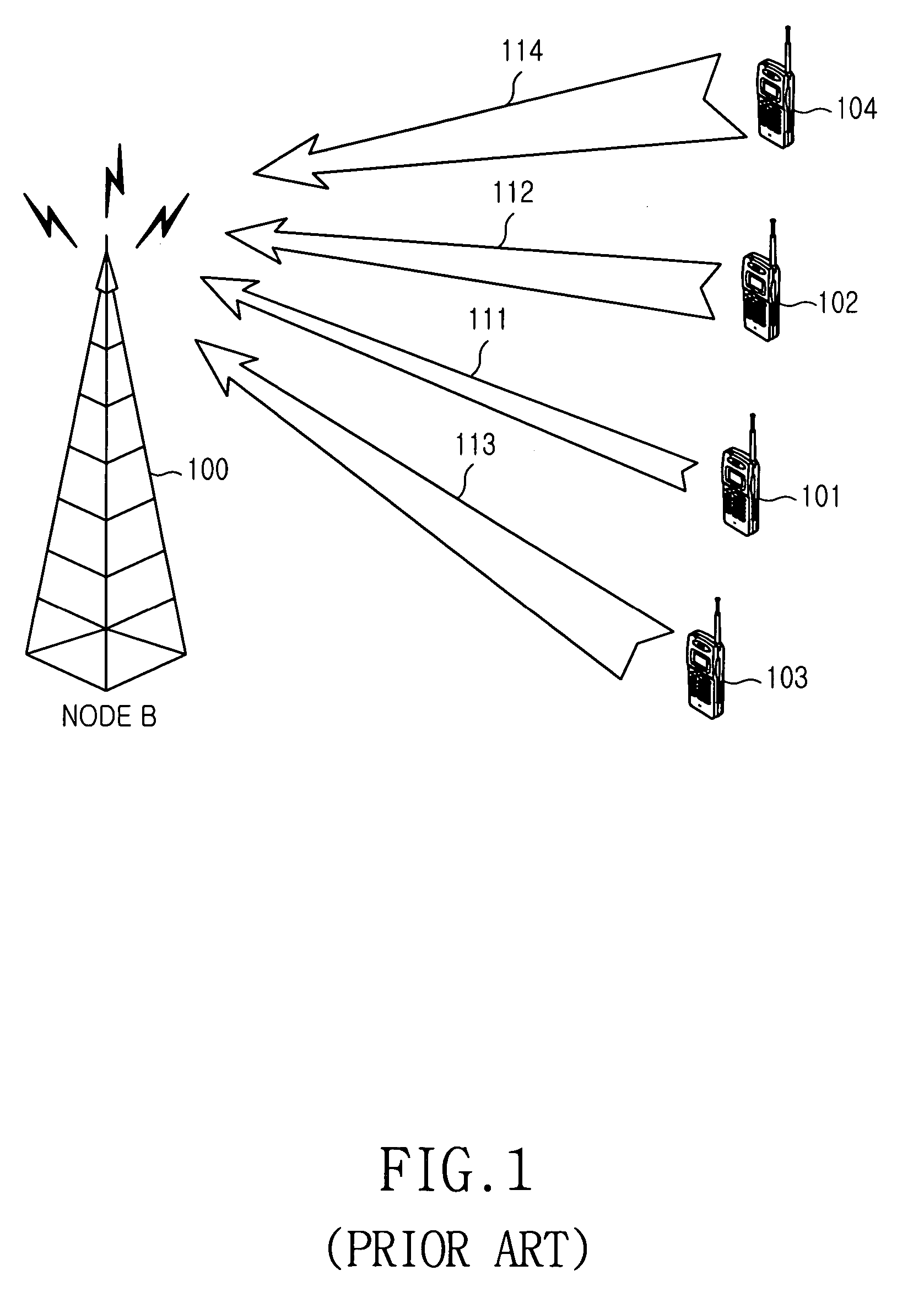
Such a method is called “maximum CQI (Channel Quality Indicator) scheduling.” However, in this method, the Node B has no information on a transmission power margin available for each UE, increasing possibility that flexibility of scheduling will be lost.
That is, even though more resources are assigned to a UE having a good uplink channel environment, if a transmission power margin of the UE is not sufficient, the UE cannot sufficiently use the assigned resources.
In addition, although the UE can be assigned a relatively high data rate in transmitting data, if a transmission power margin of the UE is not sufficient, the UE, in some cases, cannot use maximum resources determined by the Node B 100.
However, in this method, the Node B cannot accurately detect a channel condition of each UE.
Therefore, the maximum CQI scheduling method that performs scheduling according to a channel condition cannot be used.
In this case, even the UE having a large power margin, when its channel environment is poor, cannot be sufficiently assigned as many resources as the value for which the power margin is considered.
That is, even though sufficient resources as determined by the power margin are assigned, normal data transmission / reception becomes difficult due to the poor channel environment, causing a reduction in channel capacity.
The above-stated two proposed conventional methods lack information for optimized scheduling.

Method used


Image

  • Method for determining data rate of user equipment supporting EUDCH service
  • Method for determining data rate of user equipment supporting EUDCH service
  • Method for determining data rate of user equipment supporting EUDCH service

Examples


first embodiment

[0058]As a method for sending the two types of information to the Node B, there is a possible method in which the UE directly transmits both of the two types of information to the Node B over a physical channel. This method will be described later with reference to a

[0059]Meanwhile, the two types of information, i.e., transmission power information and transmission power margin information as uplink channel information, have the following relation defined as

Txpower+Txmargin=Txtotal—power  (1)

[0060]Referring to Equation (1), the total transmission power can be expressed as the sum of the transmission power and a transmission power margin value.

[0061]However, a value of the total transmission power can be determined by transmission power class information of the UE that each UE transmits to the Node B according to its UE capability. That is, each UE is designated a unique UE transmission power class, and this means that in Equation (1), the UE's total transmission power value is indiv...

seventh embodiment

[0066]The first to seventh embodiment of the present invention, for most efficiently signaling the two types of information, i.e., the UE's transmission power information (or UE's transmission power margin information) and the UE's total transmission power information, to the Node B will now be described with reference to FIGS. 4 to 10.

[0067]First Embodiment

[0068]The first embodiment provides a method for directly transmitting the above-mentioned two types of information to a Node B over a physical channel. The two types of information, as mentioned above, refer to UE's uplink channel condition information and UE's transmission power margin information. The uplink channel condition information can represent UE's transmission power information, or other information including the channel condition information. The first embodiment will now be described below with reference to FIG. 4.

[0069]FIG. 4 schematically illustrates a system using EUDCH. An RNC 410 controls one or more Node Bs, a...

second embodiment

[0087

[0088]The second embodiment will now be described below. In this embodiment, a UE sends only uplink channel condition information such as uplink transmission power over a physical channel. On the other hand, a Node B receives the UE's total transmission power information from an RNC through Iub signaling. A message signaled through Iub connection is called an NBAP (Node B Application Part) message. For the NBAP message necessary for a newly-defined EUDCH, a new message can be defined or the existing messages can be partially modified. The UEs' total transmission power information of the RNC is included in the NBAP messages necessary for the EUDCH before being transmitted. The UEs are also UEs desiring to use the EUDCH.

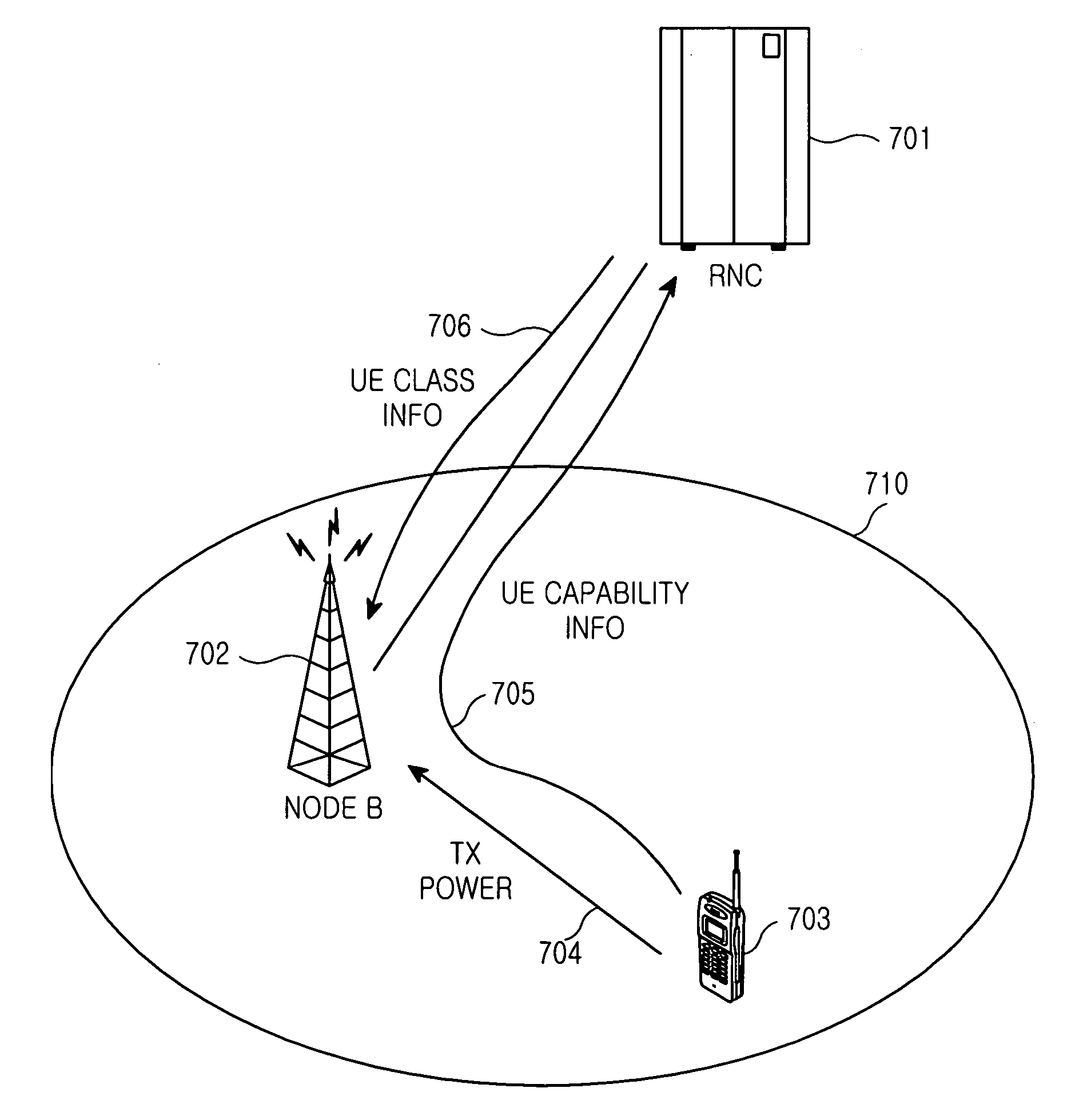
[0089]FIG. 7 is a detailed diagram illustrating the method proposed in the second embodiment. In FIG. 7, a UE 703 is receiving an EUDCH service, and an RNC 701 controls the UE 703. The RNC 701 can determine UE capability of the UE 703 through an RRC message 705 ca...


PUM


Abstract

Disclosed is a method for determining a data rate of a user equipment (UE) for an enhanced uplink dedicated channel (EUDCH) service by a Node B in a mobile communication system having a radio network controller (RNC), the UE transmitting UE transmission power class information to the RNC, and the Node B having a table for storing total transmission power corresponding to the transmission power class, the Node B supporting the EUDCH service of the UE. The method comprises receiving uplink channel condition information of the UE from the UE, and receiving UE transmission power class information from the RNC; and reading total transmission power corresponding to the received UE transmission power class from the table, and determining a data rate of the UE considering the uplink channel condition information and the total transmission power.

Description

PRIORITY[0001]This application claims priority under 35 U.S.C. § 119 to an application entitled “Method for Determining Data Rate of User Equipment Supporting EUDCH Service” filed in the Korean Intellectual Property Office on Jan. 4, 2003 and assigned Serial No. 2003-466, and an application entitled “Method for Determining Data Rate of User Equipment Supporting EUDCH Service” filed in the Korean Intellectual Property Office on Dec. 18, 2003 and assigned Ser. No. 2003-93243, the contents of both of which are incorporated herein by reference.BACKGROUND OF THE INVENTION[0002]1. Field of the Invention[0003]The present invention relates generally to a mobile communication system supporting an enhanced uplink dedicated channel (hereinafter referred to as “EUDCH”) service, and in particular, to a method for determining a data rate for an EUDCH service of a user equipment (UE) by a Node B in performing control scheduling on the UE.[0004]2. Description of the Related Art[0005]The present inv...

Claims


Application Information

Patent Timeline
IPC IPC(8): H04Q7/20H04B7/005H04J13/00H04W28/00H04W28/22H04W52/26H04W52/34H04W52/36
CPCH04W28/22H04W52/262H04W52/267H04W52/34H04W52/36
Inventor KWAK, YONG-JUNCHOI, SUNG-HOLEE, JU-HOHEO, YOUN-HYOUNG
Owner SAMSUNG ELECTRONICS CO LTD
Learn More