Apparatus, system, and method for estimating ash accumulation

a technology of ash accumulation and ash filter, applied in mechanical apparatus, non-fuel substance addition to fuel, machines/engines, etc., can solve the problems of high recovery cost, affecting engine performance, and high temperature of filter components, so as to reduce the cost of regeneration

Active Publication Date: 2007-03-15
CUMMINS INC
View PDF18 Cites 25 Cited by
  • Summary
  • Abstract
  • Description
  • Claims
  • Application Information

AI Technical Summary

Benefits of technology

[0027] In one embodiment, a soot calculation module calculates a soot accumulation as a second particulate accumulation calculated by the interpolation module minus the second ash accumulation estimate. The regeneration module may regenerate the filter if the soot accumulation exceeds a soot estimate. The method estimates ash accumulation to determine when to regenerate the filter in order to meet filter performance requirements while reducing regeneration costs.

Problems solved by technology

Accumulation of particulate matter typically causes backpressure within the exhaust system that can impair engine performance.
Excessive soot buildup on the filter can precipitate uncontrolled regeneration of a particulate filter, or, in other words, cause rapid oxidation rates resulting in higher than designed temperatures within the filter.
Recovery can be an expensive process.
Interval based regeneration, however, has proven to be ineffective for several reasons.
First, regenerating a particulate filter without particulate buildup lessens the fuel economy of the engine and exposes the particulate filter to unnecessary temperature cycles.
Secondly, if particulate matter accumulates significantly before the next regeneration, backpressure from blockage of the exhaust flow can negatively affect engine performance.
In addition, regeneration (controlled or uncontrolled) of a particulate filter containing large quantities of particulate buildup can potentially cause filter failure or the like.
Unfortunately, the accumulation of ash in the particulate filter may distort the differential pressure-based estimate, causing the premature regeneration of the particulate filter.
Current methods of estimating accumulated particulates cannot differentiate between soot and ash.
Unfortunately, the accumulation of ash in the particulate filter increases the backpressure of the exhaust gas after-treatment system.

Method used

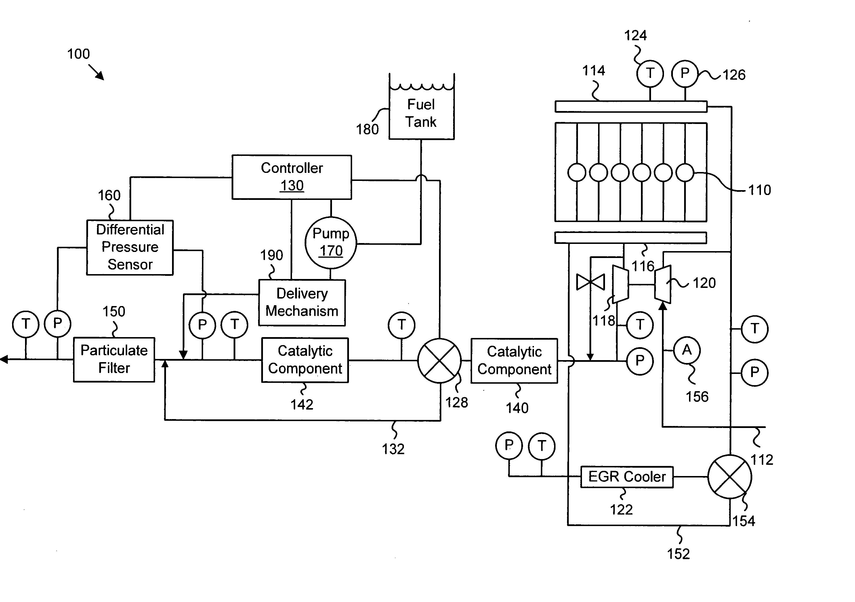
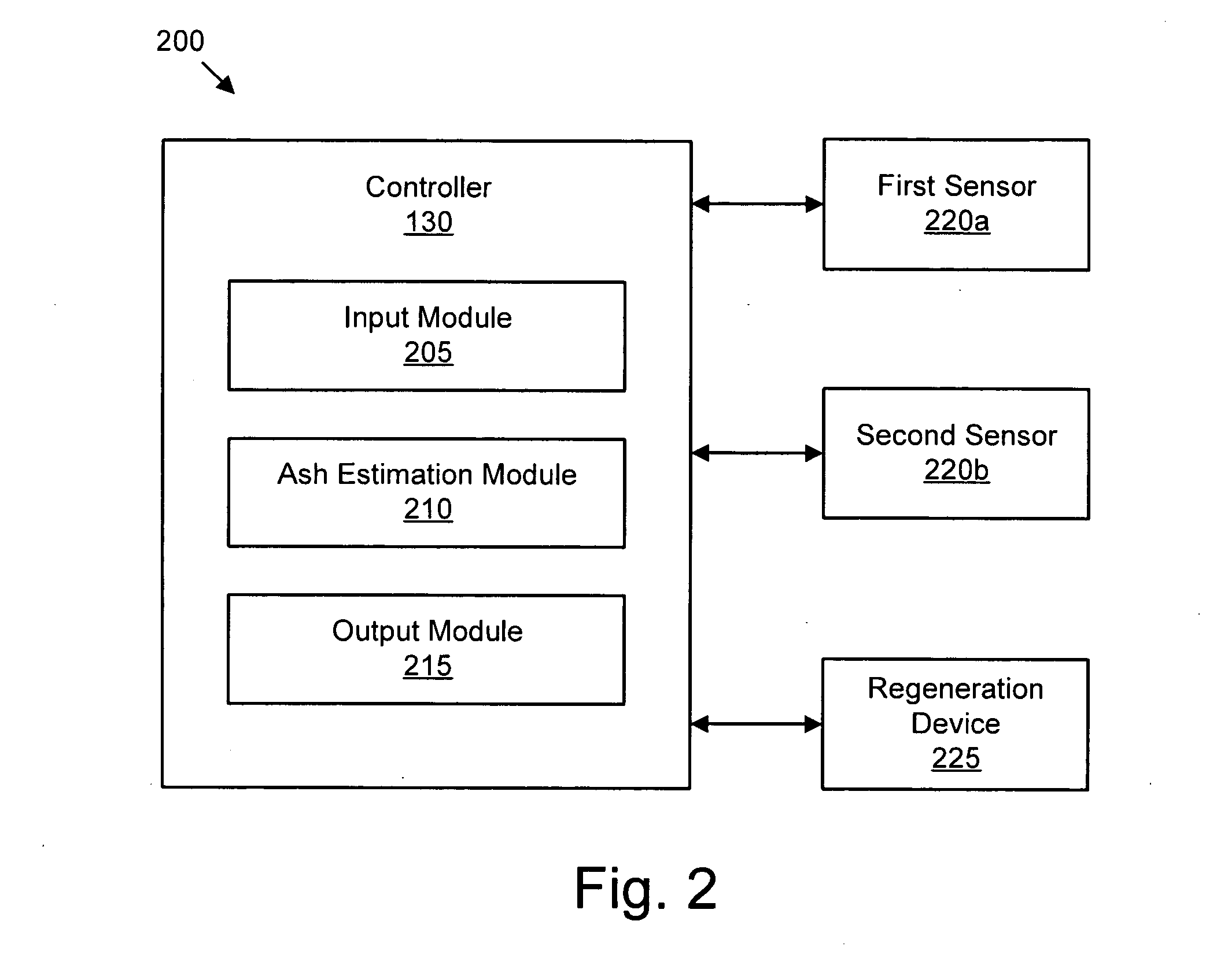

Image

  • Apparatus, system, and method for estimating ash accumulation
  • Apparatus, system, and method for estimating ash accumulation
  • Apparatus, system, and method for estimating ash accumulation

Examples


Embodiment Construction

[0047] Many of the functional units described in this specification have been labeled as modules, in order to more particularly emphasize their implementation independence. For example, a module may be implemented as a hardware circuit comprising custom VLSI circuits or gate arrays, off-the-shelf semiconductors such as logic chips, transistors, or other discrete components. A module may also be implemented in programmable hardware devices such as field programmable gate arrays, programmable array logic, programmable logic devices or the like.

[0048] Modules may also be implemented in software for execution by various types of processors. An identified module of executable code may, for instance, comprise one or more physical or logical blocks of computer instructions, which may, for instance, be organized as an object, procedure, or function. Nevertheless, the executables of an identified module need not be physically located together, but may comprise disparate instructions stored ...


PUM


Abstract

An apparatus, system, and method are disclosed for estimating ash accumulation. An interpolation module calculates a first particulate accumulation from an interpolation function. An ash feedback module calculates an ash accumulation as an ash feedback function of the first particulate accumulation and a stored first ash accumulation estimate. In one embodiment, an ash feedforward module calculates an added ash estimate. An ash accumulation module may calculate a second ash accumulation estimate as the sum of the ash accumulation and the added ash estimate. A regeneration module may deep clean the filter if the second ash accumulation estimate exceeds an ash threshold. In one embodiment, a soot calculation module calculates a soot accumulation as a second particulate accumulation minus the second ash accumulation estimate.

Description

BACKGROUND OF THE INVENTION [0001] 1. Field of the Invention [0002] This invention relates to estimating ash accumulation and more particularly relates to estimating the ash accumulation in a soot filter. [0003] 2. Description of the Related Art [0004] Environmental concerns have motivated the implementation of emission requirements for internal combustion engines throughout much of the world. Governmental agencies, such as the Environmental Protection Agency (“EPA”) in the United States, carefully monitor the emission quality of engines and set acceptable emission standards, to which all engines must comply. Generally, emission requirements vary according to engine type. Emission tests for compression-ignition or diesel engines typically monitor the release of diesel particulate matter (“PM”), nitrogen oxides (“NO,”), hydrocarbons (“HC”), and carbon monoxide (“CO”). Catalytic converters implemented in an exhaust gas after-treatment system have been used to eliminate many of the pol...

Claims


Application Information

Patent Timeline
Patent Type & Authority Applications(United States)
IPC IPC(8): F01N3/00
CPCF01N3/0253F01N13/009F01N3/2053F01N9/002F01N9/005F01N9/007F01N11/002F01N2410/00F01N2410/12F01N2610/03F02B37/00F02M25/0707F02M25/0728F02M25/0754Y02T10/144Y02T10/47F01N13/0093F01N3/035F02M26/05F02M26/25F02M26/47Y02T10/12Y02T10/40
Inventor LIIMATTA, BRIAN P.SHOOK, PATRICK J.WILLS, J. STEVEWILLS, JOAN
Owner CUMMINS INC
Why Eureka
Try Eureka