Electrical junction box

a junction box and electric technology, applied in the direction of electrical/fluid circuit, casing/cabinet/drawer, electrical apparatus details, etc., can solve the problem that water may still enter the gap between the inner wall of the case body

Pending Publication Date: 2021-03-18
SUMITOMO WIRING SYST LTD +1
View PDF15 Cites 2 Cited by
  • Summary
  • Abstract
  • Description
  • Claims
  • Application Information

AI Technical Summary

Benefits of technology

[0005]It is an object of the present invention is to provide an electrical

Problems solved by technology

However, water may still enter the gap between the inner w

Method used


Image

  • Electrical junction box
  • Electrical junction box
  • Electrical junction box

Examples


Embodiment Construction

[0030]This description provides a comprehensive understanding of the methods, apparatuses, and / or systems described. Modifications and equivalents of the methods, apparatuses, and / or systems described are apparent to one of ordinary skill in the art. Sequences of operations are exemplary, and may be changed as apparent to one of ordinary skill in the art, with the exception of operations necessarily occurring in a certain order. Descriptions of functions and constructions that are well known to one of ordinary skill in the art may be omitted.

[0031]Exemplary embodiments may have different forms, and are not limited to the examples described. However, the examples described are thorough and complete, and convey the full scope of the disclosure to one of ordinary skill in the art.

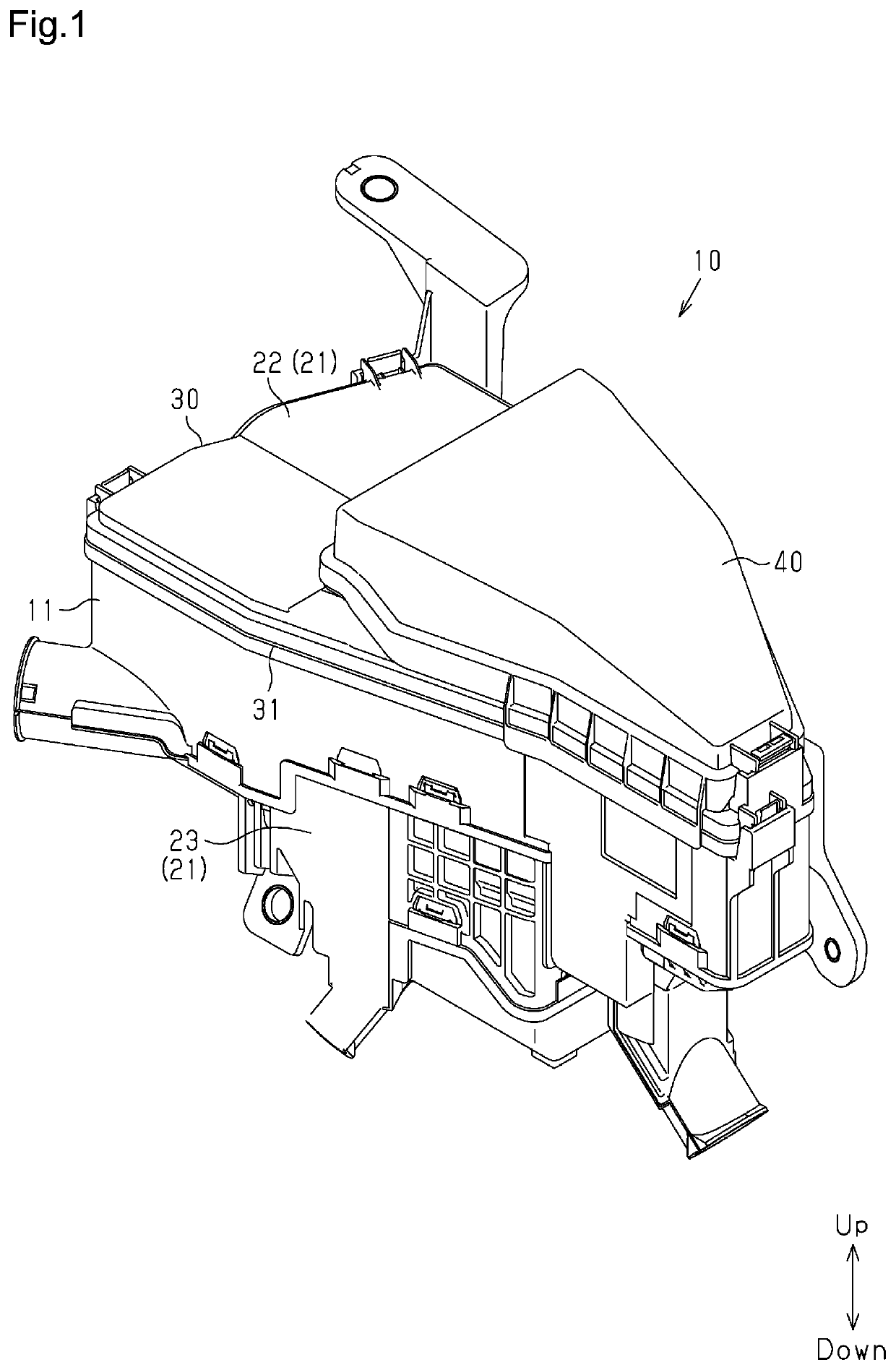
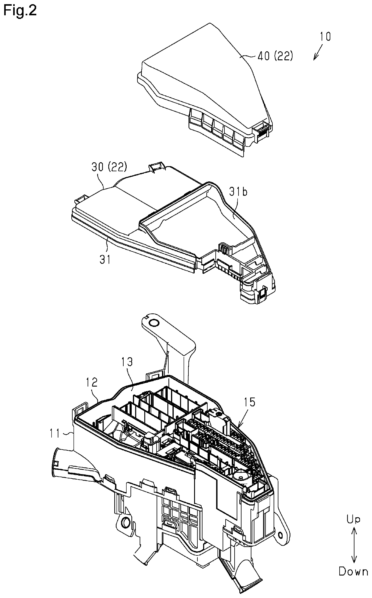
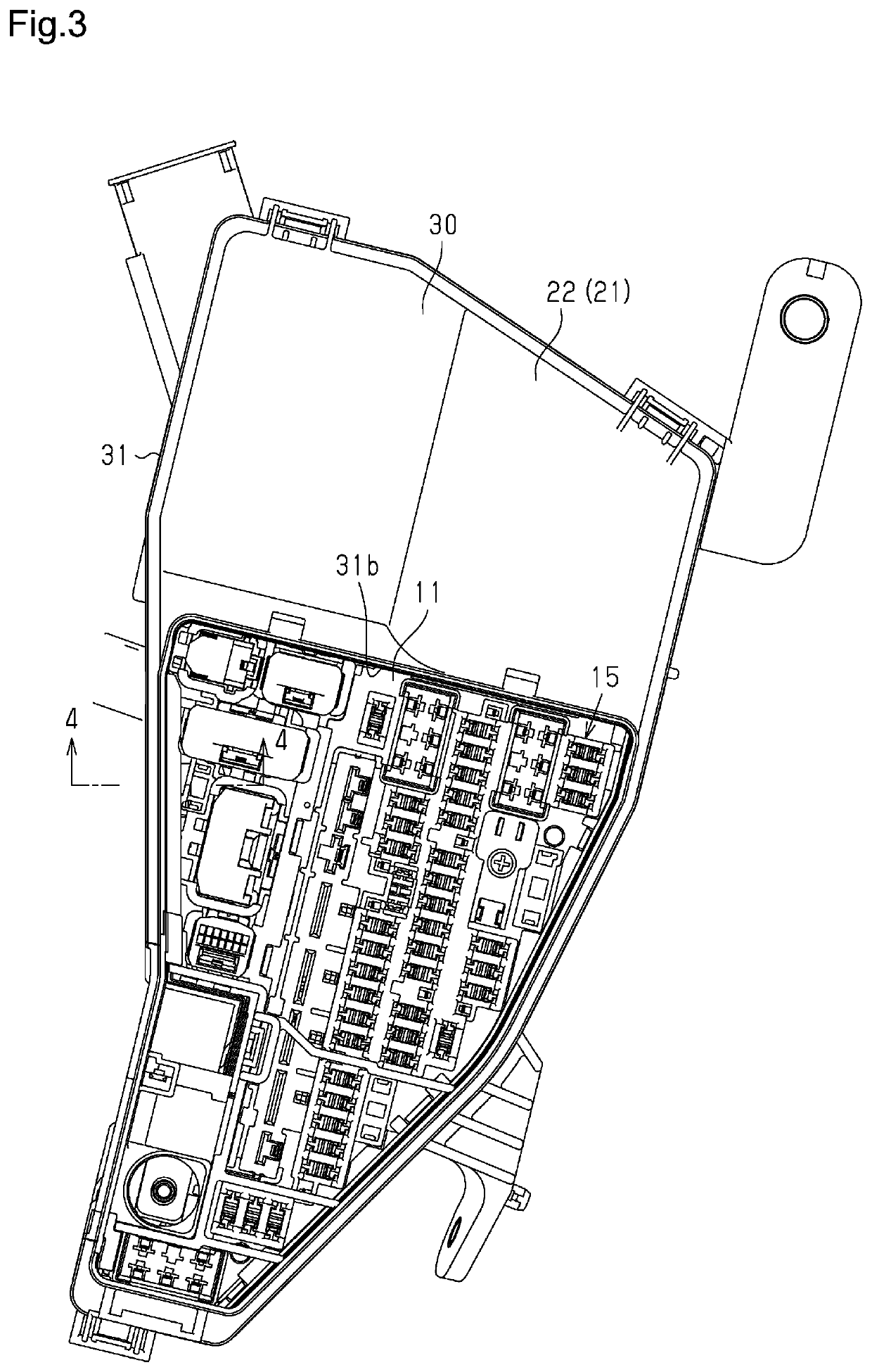
[0032]One embodiment of an electrical junction box will now be described.

[0033]As shown in FIG. 1, an electrical junction box 10 includes a case body 11 and a cover 21 coupled to the case body 11.

[0034]The ele...


PUM


Abstract

A cover-side peripheral wall includes an inner wall, which serves as a first wall, and a bent wall. The inner wall is located between an inner wall and an outer wall of a body-side double-wall. The bent wall extends inward and downward from an inner surface of the inner wall. The bent wall has a proximal end that is located upward from an upper end of the inner wall of a body-side peripheral wall. The bent wall further includes a portion between a distal end and the proximal end that is located inward and downward from the upper end of the inner wall of the body-side peripheral wall.

Description

1. FIELD[0001]The present disclosure relates to an electrical junction box.2. DESCRIPTION OF RELATED ART[0002]A conventional electric connector that is mounted on a vehicle accommodates electronic components such as relays and fuses (for example, refer to Japanese Laid-Open Patent Publication No. 2013-34320).[0003]The electrical junction box of the above patent publication includes an upper cover arranged at the upper side of a case body. The upper cover and the case body each have a double-wall structure including an outer wall and an inner wall. In the structure, the outer wall of the case body is located at the inner side of the outer wall of the upper cover, the inner wall of the upper cover is located at the inner side of the outer wall of the case body, and the inner wall of the case body is located at the inner side of the inner wall of the upper cover. This protects the electronic components accommodated in the electrical junction box from water.[0004]In an electrical juncti...

Claims


Application Information

Patent Timeline
IPC IPC(8): H02G3/08B60R16/023
CPCH02G3/086B60R16/0238H05K5/0217H05K5/03H05K5/063B60R16/02H02G3/088
Inventor WASHIHIRA, KENICHISHIRAKI, TAKASHIMIYAMOTO, YUJIKAWAI, TAKANORIKAWAI, TAKUMA
Owner SUMITOMO WIRING SYST LTD
Why Eureka
Try Eureka