Distance measuring apparatus
- Summary
- Abstract
- Description
- Claims
- Application Information
AI Technical Summary
Benefits of technology
Problems solved by technology
Method used
Image

Examples
Example
First Embodiment
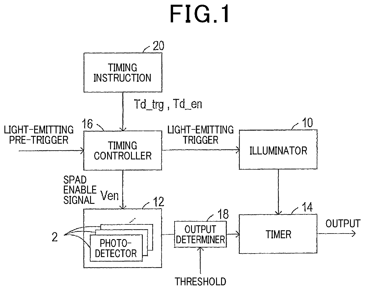
[0045]A distance measuring apparatus in this embodiment is mounted in, for example, a vehicle to measure a distance to an obstacle existing around the vehicle and, as illustrated in FIG. 1, equipped with the illuminator 10, the detector 12 equipped with a plurality of photodetectors 2, the time measuring unit 14, and the timing controller 16.
[0046]The illuminator 10 is configured to emit distance-measuring light outside the vehicle and made of an electrical circuit equipped with a light emitting device implemented by, for example, a light emitting diode working to emit a laser. The illuminator 10 activates the light emitting diode in response to a light-emitting trigger inputted from the timing controller 16 to emit distance-measuring light in the form of a laser beam in a given direction.
[0047]The detector 12 works to detect light resulting from reflection of light, as emitted from illuminator 10, on an object and is made of a matrix of the photodetectors 2 arranged...
Example
Second Embodiment
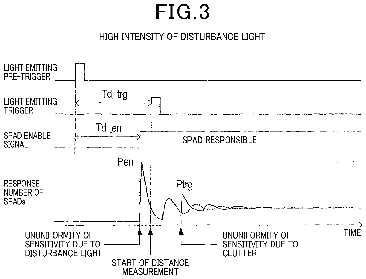
[0088]The first embodiment has been explained as being equipped with the timing controller 16 working to determine the light-emitting standby time Td_trg that is a time interval between input of the light-emitting pre-trigger to the timing controller 16 and output of the light-emitting trigger to the illuminator 10 and the detection standby time Td_en that is a time interval between the input of the light-emitting pre-trigger to the timing controller 16 and output of the enable signal Ven to the detector 12 using the timing instructing unit 20.
[0089]In contrast to the above, the distance measuring apparatus in this embodiment is, as illustrated in FIG. 8, designed to have the timing instructing unit 20 made of an arithmetic processing circuit, such as a microcomputer, which automatically determines the light-emitting standby time Td_trg and the detection standby time Td_en.
[0090]Specifically, in this embodiment, the output determiner 18 includes the adder 18A and th...
Example
Third Embodiment
[0110]The second embodiment is equipped with the peak detector 22 in order to automatically determine the light emission timing of the illuminator 10 and the activation start timing of the detector 12 depending upon surrounding environments of the vehicle.
[0111]The peak detector 22, as described above, detects maximum values of the response numbers Ptrg and Pen of the SPADs which have substantially simultaneously responded to the clutter and the disturbance light. The timing instructing unit 20 determines the standby times Td_trg and Td_en using the maximum values detected by the peak detector 22.
[0112]In contrast to the above, this embodiment is, as clearly illustrated in FIG. 11, designed to have the timing instructing unit 20 to which vehicle information about an actual positon of the vehicle, a current time, and / or weather conditions is inputted from the in-vehicle device 30.
[0113]The timing instructing unit 20 is, like in the second embodiment, made of an arithm...
PUM
 Abstract
Description
Claims
Application Information
 - R&D Engineer
- R&D Manager
- IP Professional
- Industry Leading Data Capabilities
- Powerful AI technology
- Patent DNA Extraction
Browse by: Latest US Patents, China's latest patents, Technical Efficacy Thesaurus, Application Domain, Technology Topic.
© 2024 PatSnap. All rights reserved.Legal|Privacy policy|Modern Slavery Act Transparency Statement|Sitemap