Tire Inflator

a tire inflator and tire technology, applied in the direction of tire measurement, vehicle components, transportation and packaging, etc., can solve the problems of high cost, simple add-on, complex and expensive, etc., and achieve the effect of high cost of large diameter bearings

Active Publication Date: 2021-04-08
FINKLE LOUIS J +1
View PDF0 Cites 1 Cited by
  • Summary
  • Abstract
  • Description
  • Claims
  • Application Information

AI Technical Summary

Benefits of technology

[0010]In accordance with another aspect of the invention, there is provided a bearingless tire inflator / bleed system. An important application of the tire inflator / bleed system is to off road vehicles which require adjusting tire pressure for various terrain. Such vehicles often encounter water and mud, and bearings often fail in these environments. In one embodiment, the tire inflator / bleed system avoids bearings to avoid failures and the high cost of large diameter bearings.

Problems solved by technology

The device of the '043 patent provides the desired function, but is complex and expensive, and is not a simple add-on to existing vehicles.
Other patents and patent applications disclose similar systems, but also are complex and not suitable as add-ons to existing vehicles.

Method used


Image

  • Tire Inflator
  • Tire Inflator
  • Tire Inflator

Examples


Embodiment Construction

[0026]The following description is of the best mode presently contemplated for carrying out the invention. This description is not to be taken in a limiting sense, but is made merely for the purpose of describing one or more preferred embodiments of the invention. The scope of the invention should be determined with reference to the claims.

[0027]Where the terms “about” or “generally” are associated with an element of the invention, it is intended to describe a feature's appearance to the human eye or human perception, and not a precise measurement.

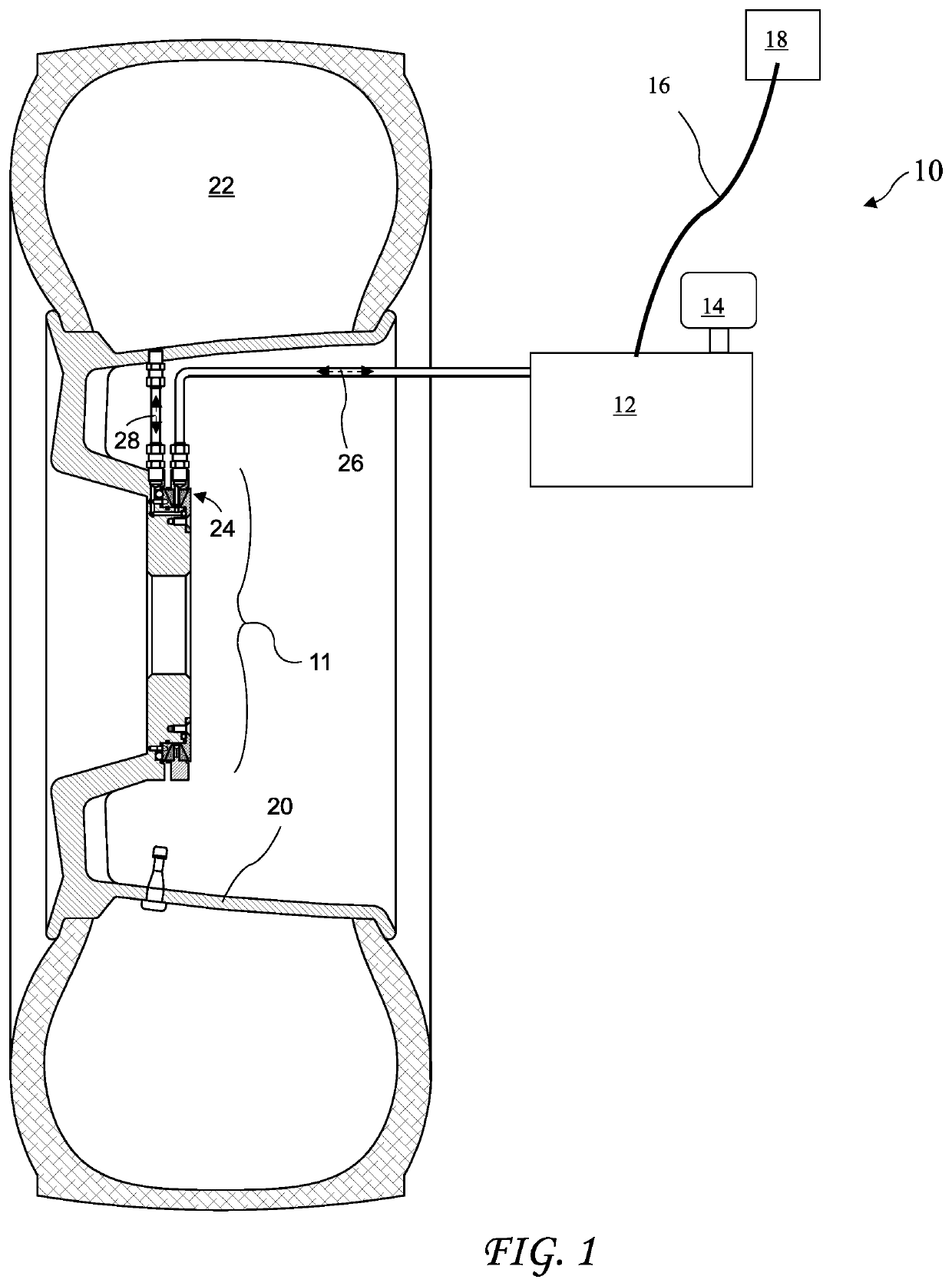
[0028]A first vehicle tire inflator / bleed 10 integrated into a wheel 20 is shown in FIG. 1. A center portion of the wheel 20 corresponds to a disk 11 of the vehicle tire inflator / bleed 10. The vehicle tire inflator / bleed 10 includes an air supply / bleed unit 12, an air filter 14, a control cable 16, a control 18, and the air transfer assembly 24. The air supply / bleed unit 12 includes an air source, for example a compressed air tank or an ai...


PUM


Abstract

A tire inflator / bleed system allows tire pressure to be adjusted using controls in a vehicle and while in motion. The inflator system includes a disk portion which rotates with a wheel, and a ring portion rotatably attached to the disk. The disk may be a spacer between the wheel and a vehicle hub, be part of the wheel, or be part of the hub. The ring portion receives air from an air supply / bleeder and is in fluid communication with the disk portion to provide the air to or from the disk portion. The disk portion is in fluid communication with a tire interior to add or remove air from the tire.

Description

BACKGROUND OF THE INVENTION[0001]The present invention relates to inflating vehicle tires and in particular to a system allowing inflating vehicle tires on a moving vehicle.[0002]Various systems have been developed to inflate tire on moving vehicles. U.S. Pat. No. 4,431,043 for “Automatic Tire Inflation System” discloses a complex automatic tire inflation system which includes a non-rotating flange 26 over an axle 12. Air enters the flange and through an opening 76 into chamber 60 between the flange 26 and wheel 14, and through an opening 78 and into a cavity 34 in the wheel. Air is then routed into the tire. The device of the '043 patent provides the desired function, but is complex and expensive, and is not a simple add-on to existing vehicles. Other patents and patent applications disclose similar systems, but also are complex and not suitable as add-ons to existing vehicles. Therefore a need remains for a simple add-on tire inflator for existing vehicles.BRIEF SUMMARY OF THE INV...

Claims


Application Information

Patent Timeline
Patent Type & Authority Applications(United States)
IPC IPC(8): B60C23/00
CPCB60C23/003B60C23/00345
Inventor FINKLE, LOUIS J.CARALE, ROBERT
Owner FINKLE LOUIS J
Why Eureka
Try Eureka