Child seat temporary holding structure in passenger motor vehicle

a passenger motor vehicle and holding structure technology, applied in the direction of child seats, vehicle components, vehicle arrangements, etc., can solve the problems of child seats falling from the rack, child seats cannot be kept attached to the seat in the passenger motor vehicle, etc., and achieve the effect of improving the connectability of the connector and the connection member configuration

Active Publication Date: 2021-04-08
TOYOTA JIDOSHA KK
View PDF0 Cites 0 Cited by
  • Summary
  • Abstract
  • Description
  • Claims
  • Application Information

AI Technical Summary

Benefits of technology

[0033]According to the disclosure of the thirteenth aspect, the connection member may be formed of one rod extending in the width direction of the child seat. Thus, the configuration of the connection member is simplified, and the connectability of the connector to the connection member is improved.
[0034]As described above, according to the present disclosure, in the passenger motor vehicle, a child seat which even an ordinary passenger can easily attach to and detach from a seat can be stored in the vicinity of the ceiling on the upper side of the vehicle body relative to the seat, without a concern that the child seat may fall.

Problems solved by technology

By the way, a child seat cannot be kept attached to a seat in a passenger motor vehicle on which an unspecified large number of people ride, such as a bus.
However, if the child seat is temporarily placed and stored on the rack set in the vicinity of the ceiling above the seat, there is a concern that the child seat may fall from the rack due to vibrations when the bus is moving.

Method used


Image

  • Child seat temporary holding structure in passenger motor vehicle
  • Child seat temporary holding structure in passenger motor vehicle
  • Child seat temporary holding structure in passenger motor vehicle

Examples


first embodiment

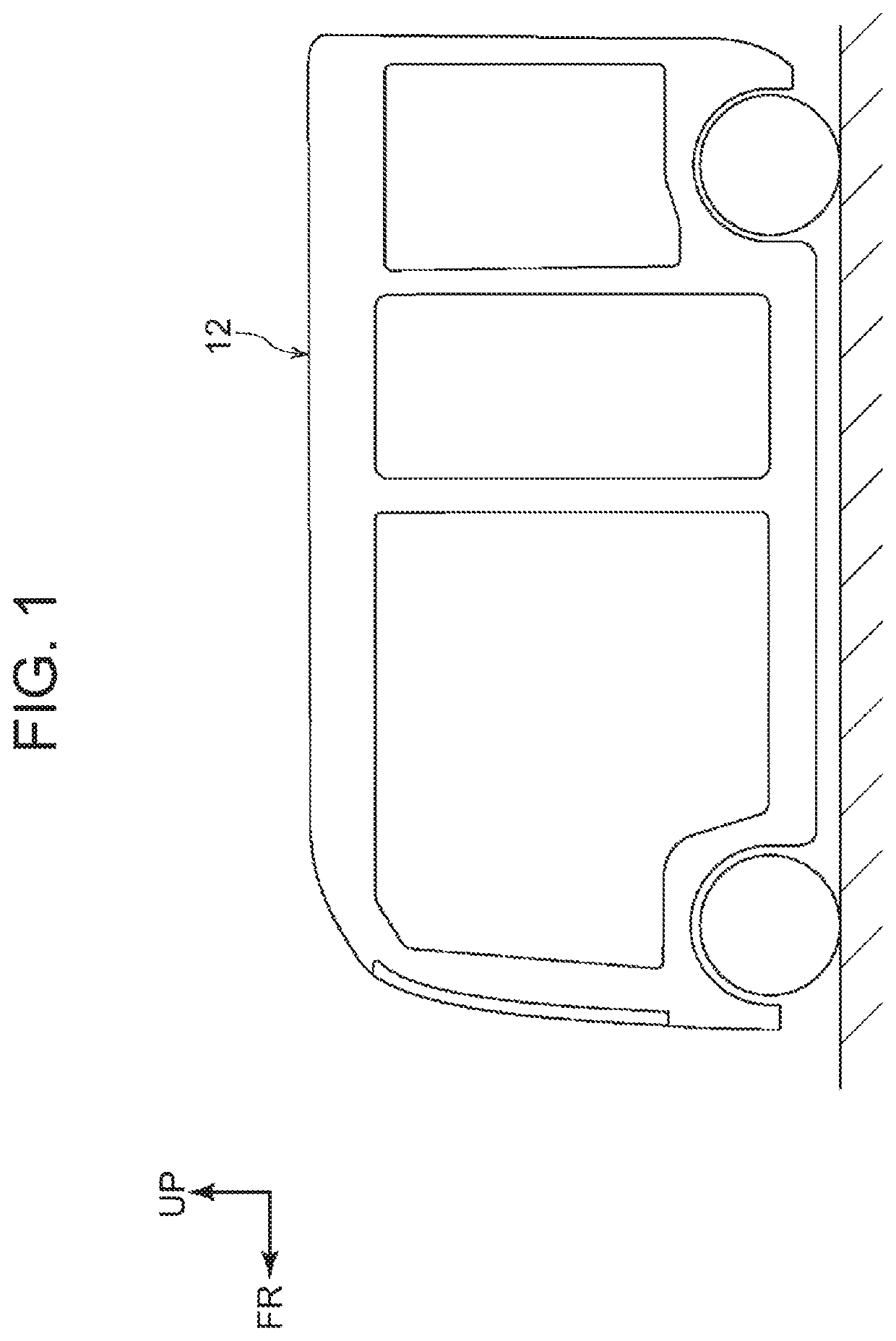
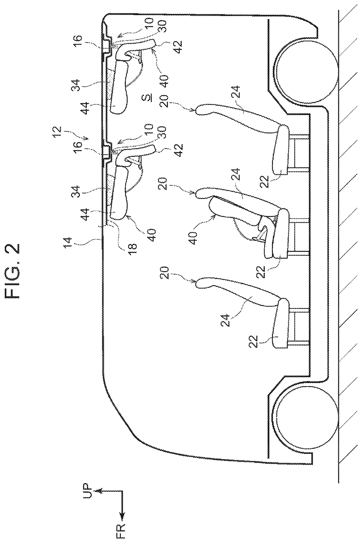
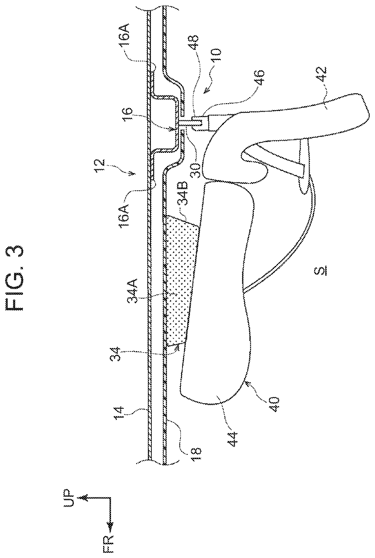
[0054]First, the first embodiment will be described. As shown in FIGS. 2 and 3, a relatively wide dead space S exists in the vicinity of the ceiling, that is, around a roof headlining 18 as a ceiling wall, on the rear side in the cabin of the bus 12 and above the seats 20. Therefore, each child seat temporary holding structure 10 is configured to store the child seat 40 in the dead space S.

[0055]More specifically, on a lower surface of a roof panel 14 made of metal constituting the roof of the bus 12, a plurality of roof reinforcements 16 made of metal extending in the vehicle width direction are provided at intervals in the front-rear direction. Each roof reinforcement 16 is formed in a substantially hat shape in a side view seen from the vehicle width direction, and each of flange portions 16A in front and rear of the roof reinforcement 16 is joined to the lower surface of the roof panel 14 by welding or the like.

[0056]A pair of left and right anchors 30 as connection members to w...

second embodiment

[0080]Next, the second embodiment will be described. Parts that are similar to those in the first embodiment are labelled with the same signs, and detailed descriptions (including the common functions) will be omitted as appropriate.

[0081]As shown in FIG. 7, the second embodiment is different from the first embodiment only in that the cushion member 34 is attached to the back surface of the seat back 44 of the child seat 40, instead of the lower surface of the roof headlining 18. Therefore, when the child seat 40 is attached to the seat 20, the child seat 40 including the cushion member 34 is attached to the seat 20.

[0082]According to the second embodiment having such a configuration, it is not necessary to attach the cushion member 34 to the roof headlining 18 of the bus 12, and therefore the interior of the bus 12 can be simplified. The cushion member 34 in the second embodiment may be formed to be thinner than the cushion member 34 in the first embodiment, so that when the cushio...

third embodiment

[0083]Next, the third embodiment will be described. Parts that are similar to those in the first embodiment are labelled with the same signs, and detailed descriptions (including the common functions) will be omitted as appropriate.

[0084]As shown in FIGS. 8, 9A and 9B, in the third embodiment, a pair of left and right anchors 30 are attached by welding or the like to a rear reinforcement 26 that is made of metal and provided on an upper part of a metal back panel 15 of the bus 12, instead of the roof reinforcement 16 provided on the roof panel 14 of the bus 12.

[0085]The rear reinforcement 26 extends in the vehicle width direction and is formed in a substantially hat shape in a side view seen from the vehicle width direction. Each of upper and lower flange parts 26A of the rear reinforcement 26 is joined to the front surface of the back panel 15 by welding or the like. A pair of left and right metal brackets 38 that pivotally support a later-described support base 36 are attached to ...


PUM


Abstract

A child seat temporary holding structure in a passenger motor vehicle having a connection member to which a connector provided on an ISOFIX type child seat is to be detachably connected, the connection member protruding from a top wall located on the upper side of the vehicle body relative to a seat in the cabin of the passenger motor vehicle.

Description

CROSS-REFERENCE TO RELATED APPLICATIONS[0001]This application claims priority to Japanese Patent Application No. 2019-184083 filed on Oct. 4, 2019, which is incorporated herein by reference in its entirety including the specification, drawings and abstract.BACKGROUND1. Technical Field[0002]The present disclosure relates to a child seat temporary holding structure in a passenger motor vehicle.2. Description of Related Art[0003]There is conventionally known a structure that enables attaching an ISOFIX type child seat to a seat by locking a pair of left and right connectors provided on the child seat to a pair of left and right metal anchors fixed to a vehicle (see, for example, Japanese Patent Application Publication No. 2002-225602).SUMMARY[0004]By the way, a child seat cannot be kept attached to a seat in a passenger motor vehicle on which an unspecified large number of people ride, such as a bus. In other words, when a toddler or an infant who needs a child seat is not on the vehic...

Claims


Application Information

Patent Timeline
Patent Type & Authority Applications(United States)
IPC IPC(8): B60N2/28B60N2/005
CPCB60N2/28B60N2/005B60R7/08B60N2/2887B60N2/3097
Inventor OHNO, MITSUYOSHI
Owner TOYOTA JIDOSHA KK
Why Eureka
Try Eureka