Solar battery module, and method of manufacturing solar battery module

a solar battery and module technology, applied in the field of solar battery modules, can solve the problems of large quantities of sealing resin that enters a softened state, deterioration of the characteristics and discoloration of sealing resin, so as to achieve the effect of simplifying the connection configuration and raising the degree of freedom for the connection configuration of the solar battery cells

Active Publication Date: 2018-06-14
SHARP KK
View PDF20 Cites 0 Cited by
  • Summary
  • Abstract
  • Description
  • Claims
  • Application Information

AI Technical Summary

Benefits of technology

[0044]As a first effect, the following effect may be exemplified. In the invention, a bus bar constituted by the first bar member and the second bar member that forms an L-shape is used, the first bar member is disposed along one side of the solar battery module to be connected to electrodes of the solar battery cells, and the second bar member is disposed along the other side of the solar battery module which perpendicularly intersects the one side. Accordingly, generated electric power of the solar battery cells can be output from either the one side or the other side (short side and long side) of the solar battery module, and thus a degree of freedom for a connection configuration of the solar battery cells is raised. As a result, it is possible to realize simplification of the connection configuration.
[0045]As a second effect of the invention, according to the solar battery module and the method of manufacturing the solar battery module according to the invention, the sealing resin is prevented from protruding from an end of the solar battery module during the sealing process, and thus it is possible to prevent the sealing resin from being bonded to the lead-out electrode.
[0046]As a third effect, according to the solar battery module and the method of manufacturing the solar battery module according to the invention, the sealing resin is prevented from protruding from an end of the solar battery module during the sealing process, and thus a positional deviation of the solar battery cells is less likely to occur.

Problems solved by technology

As a result, there is a problem that the sealing resin becomes discolored due to an increase in absorption of moisture in the sealing resin, or deterioration in characteristics of the solar battery cells tends to occur.
In addition, there is also a problem that in the sealing process, the sealing resin that enters a softened state protrudes in large quantities from an end of the solar battery module.

Method used


Image

  • Solar battery module, and method of manufacturing solar battery module
  • Solar battery module, and method of manufacturing solar battery module
  • Solar battery module, and method of manufacturing solar battery module

Examples


embodiment 1

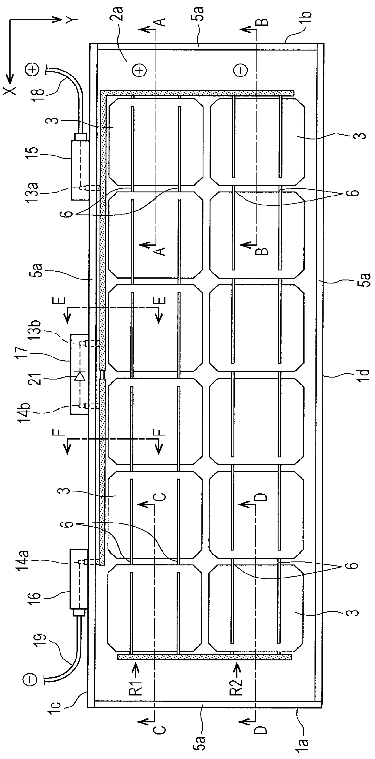
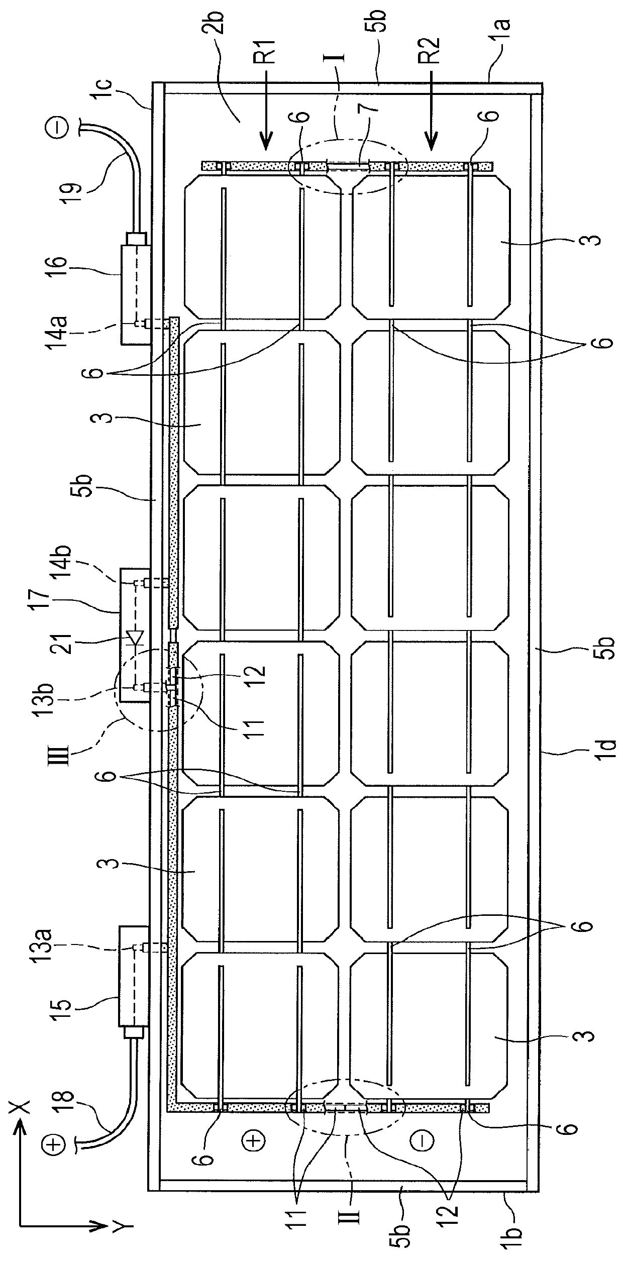
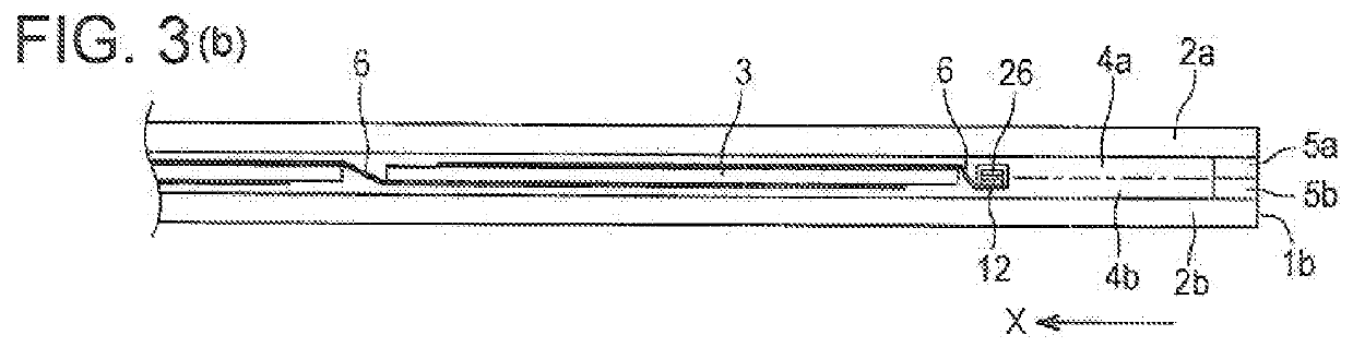
[0085]FIGS. 1 and 2 are a plan view and a rear view of a solar battery module relating to Embodiment 1 of the invention when viewed from a surface (light-receiving surface) side and from a rear surface side, respectively. In addition, FIGS. 3(a), 3(b), 3(c), and 3(d) are cross-sectional views taken along line A-A of FIG. 1, line B-B of FIG. 1, line C-C of FIG. 1, and line D-D of FIG. 1, respectively. In addition, FIGS. 4(a) and 4(b) are cross-sectional views taken along line E-E of FIG. 1 and line F-F of FIG. 1, respectively. In addition, FIG. 5 is a cross-sectional view illustrating the vicinity of an output terminal of the solar battery module of FIG. 1. In addition, FIGS. 6(a), 6(b), and 6(c) are enlarged views illustrating a portion I, a portion II, and a portion III in FIG. 2, respectively. Furthermore, in FIGS. 1 to 5, a horizontal direction is set as X, and a vertical direction is set as Y.

[0086]As shown in FIGS. 1 to 6, a solar battery module 1 has a configuration in which a...

embodiment 2

[0160]FIG. 18 is a plan view illustrating a structure of a solar battery module 100 of this embodiment when viewed from a light-receiving surface side. The light-receiving surface represents a surface on a surface side in which the solar battery cells receive light to convert optical energy to electric power.

[0161]To obtain output power sufficient for the solar battery module 100, a plurality of solar battery cells 102 are electrically connected to each other in series by using an internal wire 104 to constitute a solar battery string 105, and a plurality of the solar battery strings 105 are electrically connected to each other.

[0162]The solar battery module 100 includes two lead-out electrodes 141 on a positive electrode side and a negative electrode side. Ends on one side of the lead-out electrodes 141 are electrically connected to the solar battery cells, and although not shown in the drawing, ends on the opposite side of the lead-out electrodes are connected to a terminal box.

[0...

embodiment 3

[0204]Still another example of the invention will be described with reference to Embodiment 3. Embodiment 3 is different from Embodiment 2 in that at least a part of the lead-out electrode is coated with a protective film. The same reference numerals are given to the same configurations as Embodiment 2, and a detailed description thereof will not be repeated.

[0205]FIG. 26 is a plan view of a solar battery module 110, which is manufactured in this embodiment, when viewed from the light-receiving surface side. A lead-out electrode 141 in which a part is coated with a protective film 144 is led out to the outside of a solar battery module 110 from between adjacent protrusion prevention walls. The lead-out electrode 141 that is led out is electrically connected to a terminal stage 113 inside a terminal box 111, and thus an outer connection cable 112 and solar battery cells are electrically connected.

[0206]FIG. 27 is an enlarged cross-sectional view illustrating a lead-out portion F of t...


PUM


Abstract

L-shaped positive electrode bus bar 11 and negative electrode bus bar 12 are provided along a vertical side 1b and a horizontal side 1c of the solar battery module 1, positive electrode output terminals 13a and 13b, and negative electrode output terminals 14a and 14b are led out from the long horizontal side 1c, and a positive electrode box 15, a negative electrode box 16, and the like are provided to the long horizontal side 1c. In addition, all solar battery cells 3 of first and second rows R1 and L2 are connected in series by using only one connection bus bar 7. Accordingly, even when the positive electrode box 15, the negative electrode box 16, and the like are provided to the long horizontal side 1c of the solar battery module 1, the number of bus bars is small and the number of connection processes such as soldering is also small.

Description

[0001]This application is a divisional application of U.S. patent application Ser. No. 14 / 405,315 filed 3 Dec. 2014 (pending), which is the U.S. national phase of International Application No. PCT / JP2013 / 063035 filed 9 May 2013 which designated the U.S. and claims priority to JP 2012-126746 filed 4 Jun. 2012, JP 2012-126747 filed 4 Jun. 2012, JP 2013-005655 filed 16 Jan. 2013, JP 2013-027591 filed 15 Feb. 2013, and JP 2013-027592 filed 15 Feb. 2013, the entire contents of each of which are hereby incorporated by reference.TECHNICAL FIELD[0002]The present invention relates to a solar battery module that photoelectrically converts solar light, and a method of manufacturing the solar battery module, and more particularly, to a solar battery module with a laminated glass structure, and a method of manufacturing the solar battery module.BACKGROUND ART[0003]Various solar battery modules exist in accordance with a use or a manufacturing method thereof. As one of the solar battery modules, ...

Claims


Application Information

Patent Timeline
Patent Type & Authority Applications(United States)
IPC IPC(8): H01L31/048H01L31/02H02S40/34
CPCY02E10/50H01L31/0488H01L31/0201H02S40/34
Inventor IYATANI, KAZUSHIOKUNO, HARUOKOBAYASHI, MASAKAZUKAI, TOSHIMI
Owner SHARP KK
Why Eureka
Try Eureka