Releasable holder for cables and conduit

a technology of releasable cables and conduits, applied in the direction of electrical appliances, etc., to achieve the effect of convenient opening and closing

Active Publication Date: 2021-04-15
STICNSTAC LLC
View PDF0 Cites 0 Cited by
  • Summary
  • Abstract
  • Description
  • Claims
  • Application Information

AI Technical Summary

Benefits of technology

[0012]The releasable cable holder can secure various types and sizes of cables and wires, such as, NM cables, MC cables, Cat 5 cables, and SER cables, as well as various conduits. For example, the holders may secure conduit-protected cables and wires. The releasable cable holder may be opened and closed for adding or removing cables or wires. Furthermore, the releasable cable holder may be stacked and secured on another, similar releasable cable holder, for separating and / or adding additional cables or wires. An advantage of the stackable holder versus the staple method is that the additional cables may be placed in the center of the stud. The staple method, if wires are being added requires either placing the additional wire off-center, which might not be code-compliant, or removing the existing staple, which is time-consuming and re-stapling with the additional wire, which also might not be code-compliant. Additional advantages include the lighter weight of the holders versus staples-plus-hammer, and elimination of the problem of striking the staple too hard with the hammer and damaging the insulation.
[0015]A hinge attaches the top and bottom covers together on one side to facilitate the opening and closing of the releasable cable holder. In many embodiments, the hinge is a flexible hinge, molded from the same material used for the primary components of the cable holder. Such a flexible hinge may also be a living hinge, with the primary components and the living hinge molded as part of a single injection process. On an opposite side of the hinge is a latching or snapping system that secures the top and bottom cover together. In some embodiments, the releasable cable holder may have a tab or flap attached to a top cover to help unlatch and / or open the releasable cable holder.

Problems solved by technology

The staple method, if wires are being added requires either placing the additional wire off-center, which might not be code-compliant, or removing the existing staple, which is time-consuming and re-stapling with the additional wire, which also might not be code-compliant.

Method used


Image

  • Releasable holder for cables and conduit
  • Releasable holder for cables and conduit
  • Releasable holder for cables and conduit

Examples


second embodiment

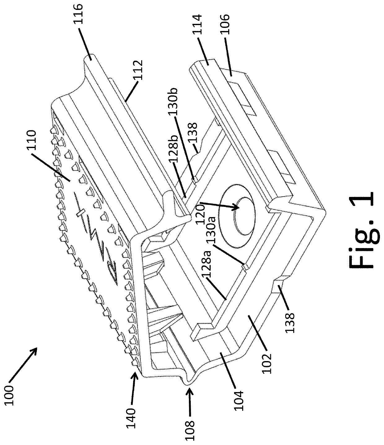
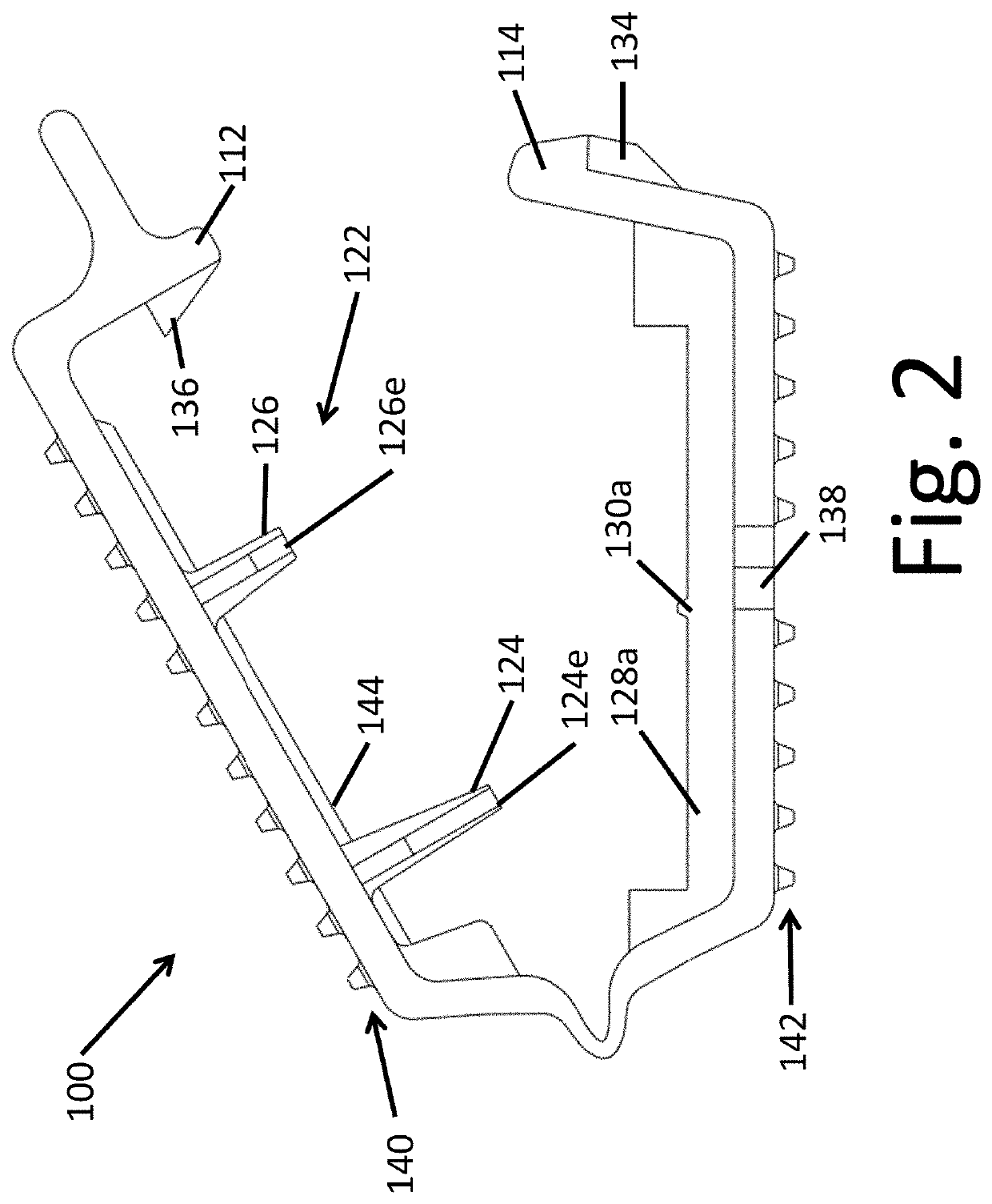
[0089]a holder 200 is shown in FIGS. 16-26. Similar features are labelled with reference numbers that are similar to those described above, but beginning with the numeral “2”, such as a base plate 202 and a top cover 210. A base set of impediments 246 are formed on base plate 202, jutting out from base plate 202 and generally facing top cover 210.

[0090]A hole 220 may be formed in base 202. Hole 220 may receive a fastener, such as a screw, nail, or rivet, to additionally connect base 202 to the underlying structure. In a finished installation, it is intended that holder 200 be firmly anchored to the underlying structure, and that holder 200 firmly grips any cable held in holder 200.

[0091]A top set of impediments 222 is formed in top cover 210, jutting out from top cover 210 and generally facing base plate 202. By forming opposing impediments, with some impediments 222 formed on top cover 210, and other impediments 246 formed on base plate 202, a cable placed on base plate 202 between...

third embodiment

[0094]a holder 300 is shown in FIGS. 27-30. Similar features are labelled with reference numbers that are similar to those described above, but beginning with the numeral “3”, such as a base plate 302 and a top cover 310. Holder 300 includes a top set of impediments 322, and a base set of impediments 346. Holder 300 is intended for use with MCC. One noticeable difference between holder 200 and holder 300 is that at least some of impediments 322 and 346 are frustoconical in shape.

fourth embodiment

[0095]a holder 400 is shown in FIGS. 31-38. Similar features are labelled with reference numbers that are similar to those described above, but beginning with the numeral “4”, such as a base plate 402 and a top cover 410. Holder 400 includes a top set of impediments 422, and a base set of impediments 444. Holder 400 is intended for use with PEX.

[0096]FIG. 30 shows overlapping lines, representing an unflexed, but inaccurate, position of latching lip 312 and corresponding lip 314. The overlap depicts the spring-like forces created between latching lip 312 and corresponding lip 314, resulting in a firm, secure latching mechanism. A more accurate representation of the third embodiment of FIG. 30 would look somewhat like what is shown in FIGS. 7 and 22.

[0097]FIGS. 37 and 38 shows similar overlapping lines, representing an unflexed, but inaccurate, position of latching lip 412 and corresponding lip 414. The overlap depicts the spring-like forces created between latching lip 412 and corres...


PUM


Abstract

A cable support for securing wires and cables to an underlying structure without the use of tools and allows the cable support to be opened or closed to add or remove cables and wires. The cable support may further include padding material or impediments for protecting and securing the wires and cables in place.

Description

CROSS-REFERENCE TO RELATED APPLICATIONS[0001]This application is a continuation of U.S. patent application Ser. No. 16 / 405,868 filed May 7, 2019, which is a continuation-in-part of U.S. patent application Ser. No. 15 / 836,766 filed Dec. 8, 2017, which is a continuation of U.S. patent application Ser. No. 15 / 239,686, filed Aug. 17, 2016, and entitled RELEASABLE HOLDER FOR CABLES AND CONDUIT, which claims priority to U.S. Provisional Patent Application Ser. No. 62 / 209,213, filed Aug. 24, 2015, and entitled RELEASABLE HOLDER FOR CABLES AND CONDUIT, the disclosure of all of which are incorporated herein in their entirety by reference.FIELD OF THE DISCLOSURE[0002]This disclosure relates to a releasable cable holder. More particularly, the disclosure relates to systems and methods for attaching and securing a wire, cable, or conduit to a structure. For example, these releasable cable holders may be used inside a wall in a residential, commercial, or industrial structure, adjacent a junctio...

Claims


Application Information

Patent Timeline
Patent Type & Authority Applications(United States)
IPC IPC(8): H02G3/32H02G3/30H02G3/04
CPCH02G3/32H02G3/0418H02G3/0487H02G3/305
Inventor GINTZ, WILLIAM GARY
Owner STICNSTAC LLC
Why Eureka
Try Eureka